Flush framed shear joist connection ("  Connection specifications ")
- Connection specifications:
- Topics:
Also see :
------"  Connection specifications " for joist ' Flush framed shear ' connections ------
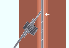
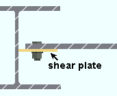
Shear plate side: Automatic or Near side or Far side or Both .
' Near side '
|
' Far side '
|
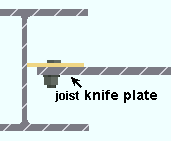
' Automatic ' specifies, when Home > Project Settings > Fabricator > Standard Fabricator Connections > Shear Plate Settings > " Shear plate alignment " is set to ' Offset ', that the shear plate be designed on the near side if this is the left end of the joist, on the far side if this is the right end of the joist. When the " Shear plate alignment " is ' Opposite ', then setting the left end to ' Automatic ' places the left-end plate/tee on the near side of the joist, and setting the right end to ' Automatic ' places the right-end plate/tee on the near side of the joist.
' Near side ' or ' Far side ' specifies the side of the joist's knife plate that the shear plate will be bolted to. The near side face of the knife plate correlates to the face of the joist that you are facing when the joist is upright and its left end is to your left and its right end is to your right.
Extend past flange: ![]() or
or ![]() . This "
. This " ![]() Connection specifications " option applies to shear plates to a beam web or to a column web. The option can be found on the Joist Edit window and at Home > Project Settings > Job > Connections > Auto Standard Connections and User Defined Connections .
Connection specifications " option applies to shear plates to a beam web or to a column web. The option can be found on the Joist Edit window and at Home > Project Settings > Job > Connections > Auto Standard Connections and User Defined Connections .
 |
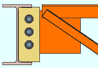 |
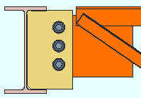
If this box is checked (
), connection design attempts to extend the shear plate past the flanges of the supporting member that the shear plate welds to. The supporting member can be a wide flange, S shape or welded plate wide flange beam or column.
If the box is not checked (
), connection design does not create an extend-past-flanges shear plate connection.
A design limitation: For joists framing to sloping beams, the angle between the beam web and a line perpendicular to the slope of the supporting beam is limited to a maximum of 15 degrees.
Connection design locks: "
Stability Plate "
Extend stabilizer plates to: Automatic or Web . This applies when -- here in " ![]() Connection specifications " -- "
Connection specifications " -- " ![]() Extend past flange " is on (checked) for a joist to a column web. Also, the option at Home > Projects Settings > Job > Design > Design Settings > "
Extend past flange " is on (checked) for a joist to a column web. Also, the option at Home > Projects Settings > Job > Design > Design Settings > " ![]() Always provide stabilizer plates " may have to be turned on (checked)
Always provide stabilizer plates " may have to be turned on (checked)
|
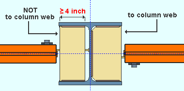
The stabilizer plate on the left is not extended since its unextended width is greater than or equal to 4 inches. The stabilizer on the right is extended because " Extend stabilizer plates to " is set to ' Web '. |
' Automatic ' permits connection design to determine whether or not to extend the stabilizer plates to the column web. The stabilizer plates will be fully extended to the web if the stability plate width (unextended) would be less than 4 inches (102 mm). A more complete explanation is provided in the Connection Guide.
' Web ' instructs connection design to extend the stabilizer plates to the column web.
Connection design locks: "
Stability Plate "
Stiffener opposite: ![]() or
or ![]() . This "
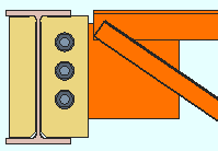
. This " ![]() Connection specifications " option applies when a beam frames to the web of a beam whose " Section size " is a flanged material such as wide flange, S shape or welded plate wide flange. To get the stiffener, something other than ' As required ' needs to be selected for " Extend size to ."
Connection specifications " option applies when a beam frames to the web of a beam whose " Section size " is a flanged material such as wide flange, S shape or welded plate wide flange. To get the stiffener, something other than ' As required ' needs to be selected for " Extend size to ."
 |
 |
If this box is checked (
), connection design is instructed to check for interference and, where no interference is detected, design a stiffener, of the same depth as that specified for " Extend size to " on the opposite side of the supporting beam's web. The stiffener will also be the same thickness as the shear plate. A lockable field for " Width of stiffener opposite " is provided in the "
Shear Tab " leaf.
If the box is not checked (
), a stiffener is not designed opposite to the shear plate.
Extend size to: As required or Top flange or Bottom flange or Both flanges or Top K or Bottom K or Both K's or Top flange & bottom K or Top K & bottom flange . This " ![]() Connection specifications " option applies to joist-to-beam shear plate connections when the supporting beam's " Section size " is a flanged material such as wide flange, S shape or welded plate wide flange. The option can be found on the Joist Edit window and at Home > Project Settings > Job > Auto Standard Connections and User Defined Connections .
Connection specifications " option applies to joist-to-beam shear plate connections when the supporting beam's " Section size " is a flanged material such as wide flange, S shape or welded plate wide flange. The option can be found on the Joist Edit window and at Home > Project Settings > Job > Auto Standard Connections and User Defined Connections .
' Top flange '

|
' Both flanges '

|
' Both K's '

|
' As required ' specifies that connection design attempt to size the shear plate as required by the framing situation and the applied " Shear load ." Note: Connection design does not design a " Stiffener opposite " when ' As required ' is selected.
' Top flange ' specifies that connection design extend the top of the shear plate to the top flange of the supporting beam.
' Bottom flange ' instructs connection design to extend the shear plate to the bottom flange of the supporting beam.
' Both flanges ' configures connection design to extend the shear plate to both flanges of the supporting beam.
' Top K ' extends the top of the shear plate to the top " k distance " of the supporting beam.
' Bottom K ' extends the bottom of the shear plate to the bottom " k distance " of the supporting beam.
' Both K's ' extends the shear plate to both the top flange and the bottom " k distance " of the supporting beam.
' Top flange & bottom K ' extends the shear plate to both the top flange and the bottom " k distance " of the supporting beam.
' Top K & bottom flange ' extends the shear plate to both the top " k distance " and the bottom flange of the supporting beam.
Try two-bolt-column shear tabs: ![]() or
or ![]() . This "
. This " ![]() Connection specifications " option can be found on the Joist Edit window and at Home > Project Settings > Job > Auto Standard Connections and User Defined Connections .
Connection specifications " option can be found on the Joist Edit window and at Home > Project Settings > Job > Auto Standard Connections and User Defined Connections .
|
|
If this box is checked (
), connection design is instructed to attempt to create a shear plate with two columns of bolts.
If the box is not checked (
), connection design is required to create the shear plate with a single bolt column.
Skew holes in plate: Automatic or Yes or No . This " ![]() Connection specifications " option applies to shear plates on slightly sloping joists.
Connection specifications " option applies to shear plates on slightly sloping joists.
|
|
' Automatic ' instructs connection design to apply a setup choice ( Home > Project Settings > Fabricator > Standard Fabricator Connections > Shear Plate Settings > " Skew holes in shear tabs ").
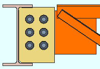
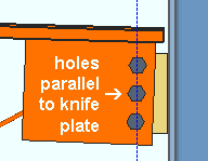
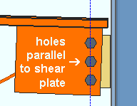
' Yes ' instructs connection design to create a shear plate with bolts skewed so that they run parallel with the framing edge of the sloping joist's knife plate.
' No ' configures connection design to create bolts that are parallel to shear plate's edge that welds to the supporting member.
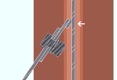
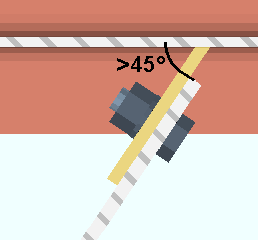
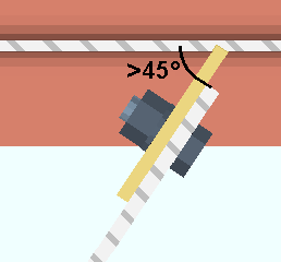
Use back-up bar: Automatic or Yes or No . This " ![]() Connection specifications " option applies to skewed joist-to-beam or joist-to-column single-plate shear connections with angles to the supported member of less than 45 degrees. Standard AISC practices call for a back-up bar to be used for such welds. The views in the following illustrations show the joist knife plate and shear plate in cross-section and are taken from below the top flange of the supporting beam.
Connection specifications " option applies to skewed joist-to-beam or joist-to-column single-plate shear connections with angles to the supported member of less than 45 degrees. Standard AISC practices call for a back-up bar to be used for such welds. The views in the following illustrations show the joist knife plate and shear plate in cross-section and are taken from below the top flange of the supporting beam.
|
|
' Automatic ' specifies that connection design apply a setup choice ( Home > Project Settings > Fabricator > Connection Detailing and Fabrication Options > " Use backing bar for pre-qualified welds ").
' Yes ' instructs connection design to create a back-up bar (the angle between members must be less than 45 degrees).
' No ' instructs connection design to not create a back-up bar.
Use alternate eccentricity: Automatic or Yes or No . This " ![]() Connection specifications " option applies to "
Connection specifications " option applies to " ![]() Extend past flange " shear connections designed using an AISC " Connection design method ." Per the AISC 13th Edition , p 10-103 and AISC 14th Edition , p 10-104, "alternate considerations of the design eccentricity are acceptable when justified by rational analysis. For example, see Sherman and Ghorbanpoor (2002)."
Extend past flange " shear connections designed using an AISC " Connection design method ." Per the AISC 13th Edition , p 10-103 and AISC 14th Edition , p 10-104, "alternate considerations of the design eccentricity are acceptable when justified by rational analysis. For example, see Sherman and Ghorbanpoor (2002)."

|
The two connection design calculation reports notify you when the alternate eccentricity calculation has been used. |
' Automatic ' specifies that connection design apply a setup choice ( Home > Project Settings > Job > Design Settings > " Use alternate eccentricity for extended shear tabs ").
' Yes ' instructs connection design to use the alternate method prescribed by Sherman and Ghorbanpoor (2002) for calculating eccentricity. In the Connection Design Calculations or Expanded Calculations , you will get a note that the " Alternate eccentricity calculation has been used " or that the " Alternate eccentricity calculation is not applicable to this connection ."
' No ' instructs connection design to use the standard method for calculating eccentricity.
Shear plate grade: Auto or user-entered . This " ![]() Connection specifications " option applies to shear plates and shear through plates, but not to shear tee connections. The option can be found on the Joist Edit window and at Home > Project Settings > Job > Connections > Auto Standard Connections and User Defined Connections .
Connection specifications " option applies to shear plates and shear through plates, but not to shear tee connections. The option can be found on the Joist Edit window and at Home > Project Settings > Job > Connections > Auto Standard Connections and User Defined Connections .
'
Auto (checked) ' specifies that connection design apply a setup choice ( Home > Project Settings > Fabricator > Standard Fabricator Connections > Plates > the " Shear Plates " section > " Plate material grade ").
'
Auto (not checked) ' lets you select a steel grade on the list box (
). Choices on the list box come from Home > Project Settings > Job > Material Grades > Plate Grades .
Bevel shear plate as required: Automatic or Yes or No .
|
' Automatic ' specifies that connection design apply a setup choice ( Home > Project Settings > Fabricator > Standard Fabricator Connections > Shear Plate Settings > " Bevel shear plate as required ").
' Yes ' configures connection design to bevel the shear plate when 5/16 - 3/8 thick plate is greater than 30° and less than 45° from perpendicular. 1/2 thick plates are beveled when the plate is greater than 22° and less than or equal to 45° from perpendicular.
' No ' instructs connection design to not bevel the shear plate.
Also see: Bevel precision ( Home > Project Settings > Fabricator > Standard Fabricator Connections > Shear Plate Settings ).
Connection design locks for shear connections :
Connection design locks for shear connections may appear, under a leaf with one of the below-listed names, on the Joist Edit window, or on a Connection Component window. They may also appear on the User Defined Connections window.
| Connection Design Locks
(" Input connection type " = ' Flush framed shear ') |
|
| Leaf Name | Situation |
| Knife Plate | The flush framed shear connection bolts to the joist's knife plate. |
| Shear Tab | Joist to a beam or column. |
| Tab Clips and Copes | Joist to a beam or column. |
| Stability Plate
|
Joist to a column web. |
