 Add Extruded Profile Member ( Modeling )
Tool summary :
- Adds a member whose length you establish by locating two points. You define the profile of the member on its edit window .
VIDEO 
An extruded profile member's origin and length is defined by locating two points in the model. Then its profile is defined on its member edit window. - Two work points are required to lay out an extruded profile member. The first point that you locate is the left end of the member. The " Left end setback " on the member's edit window pertains to the first-located-point end.
- In the following example, User and Site Options > Modeling > " Show member origin " and " Highlight surfaces " are turned on (
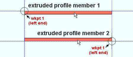
 ). The left-end work point of extruded profile member 1 is to its left. The left-end work point of extruded profile member 2 is to its right.

- When you add an extruded profile member for the first time during a Modeling session, options on the Extruded Profile Member Edit window are populated with choices made at Home > Project Settings > Job > Plugin Defaults > Member > Extruded Profile . Thereafter, during that same Modeling session, each subsequently added extruded profile member will use the settings from the extruded profile that was last added or last edited. An extruded profile member is a custom member .
- The profile of an extruded profile member can be edited under the " Material Layout " section on the Extruded Profile Member Edit window. You can also apply a " Member rotation " and a " Left end setback " and " Right end setback ."
- In Modeling , before adding an extruded profile member, you need to Open ( Ctrl + o ) a view that is appropriate for the layout. To lay out a perfectly horizontal extruded profile member, open a plan view at the desired elevation. Work points for a perfectly vertical extruded profile member can be located in an elevation view . Work points for a sloping extruded profile member should be located in a view that is at the desired slope. You may have to create such a view using View > Section View . Of course, even if you don't add the member in exactly the correct view, you can Model > Member > Move/Stretch to reposition a member after it has been added.
- To invoke Add Extruded Profile Member (in Modeling ):
Method 1 : Click the Add Extruded Profile Member icon, which is pictured above. The icon can be taken from the group named ' Model -- Member ' and placed on a toolbar (classic) or the ribbon (lightning).
Method 2 : If " Modeling layout style " is ' Classic ', you can choose Model > Member > Add Extruded Profile Member , then check the box for and double-click " Extruded Profile Member " on the Member Type Selection window.
Method 3, 4 or 5 : Add Extruded Profile Member can also be configured to be invoked using a keyboard shortcut , the context menu , or a mode . For the lightning interface, this configuration is done using Customize Interface .
Method 6 : Press F2 > select "
 Miscellaneous Steel " > click " Extruded Profile Member ."
- You can start the Add Extruded Profile Member tool in the same way as is shown in the following video when " Modeling layout style " is ' Classic '.
VIDEO 
Model > Member > Prompt for Member Type opens the Member Type Selection window, on which " Extruded Profile Member " is double-clicked. Two work points are located. On the Extruded Profile Member Edit window, the profile is defined to be an S shape.
page 1 | contents | F2 > miscellaneous steel > extruded profile member | edit window | top


