Extruded Profile Member Edit window ( Job Settings )
-
Add Extruded Profile Member (link is to another page) (
 )
)
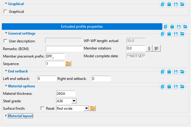


The " OK " button is disabled (grayed out) to indicate a validation error. Hover the " OK " button with your mouse pointer to get a listing of settings you need to change on this window. When all settings are valid, the " OK " button is enabled. 
Red-colored highlighting identifies an entry that is invalid. You need to change that setting, or you will not be able to close this window using " OK ."
Also see :
- Modeling (where you can add an extruded profile member)
- Custom members (topic)
- Extruded Profile setup window ( Home > Project Settings > Job > Plugin Defaults > Member ... )
------  Graphical ------
Graphical : ![]() or
or ![]() . You should check this box when you no longer want the extruded profile member to undergo Process and Create Solids . For example, when you are ready to begin manually modifying the member using material cutting operations, or etc. Click here for more information.
. You should check this box when you no longer want the extruded profile member to undergo Process and Create Solids . For example, when you are ready to begin manually modifying the member using material cutting operations, or etc. Click here for more information.
------ General information ------
If this box is checked (
), you can make an entry here that what will become, during Detail Members , the material's " Description " in the member bill of material. During Detail Submaterial , the description entered here becomes the main callout on the submaterial detail .
| " User description " entered here: |
|
|
| " Description " in member bill of material: |
|
| Description in submaterial detail callout: |

|
If the box is not checked (
), the material's " Description " in the member bill of material will, after auto detailing , be blank. The main callout on the submaterial detail will consist of the member piecemark.
Remarks (BOM): Any characters that you want to be entered automatically, during Detail Members , as the material's " Remarks " in the member bill of material.
| " Remarks (BOM) " entered here: |
|
|
| " Remarks " in member bill of material: |
|
|
Piecemark prefix: Any characters that you want to begin the member piecemark that will be assigned to the extruded profile member that you are adding. The piecemark will be assigned when the member is generated, after you press the " OK " button.
For example, if you were to type EPF_ here, and this is the 89th member you have added, SDS2 piecemarking may add 89 after this prefix, thus assigning your new extruded profile member the piecemark EPF_89 .
If you edit an extruded profile member and change its piecemark prefix, the old piecemark will continue to be used.
SDS2 piecemarking will not apply the prefix entered here if the extruded profile member you are adding is exactly like another extruded profile member with a different prefix. Piecemarking will, instead, assign the new extruded profile member the same piecemark that was assigned to the previously added extruded profile member.
Sequence: Any sequence name from the Sequence Names setup list can be entered. Either type the sequence, or you can press the "file cabinet" browse button ( ![]() ) and double-click any sequence name that is on the list.
) and double-click any sequence name that is on the list.
Tip: To add a new sequence to the Sequence Names setup list so that it can be selected here, first increase the number of " Maximum sequences " that are available.
WP-WP length: actual: Read-only . The length of this extruded profile member's member line (in the primary dimension " Units "). This distance is calculated from the X and Y and Z global coordinates of the two work points that were located when the extruded profile member was added .
|
| WKPT 1 is the 1st work point that was located when the extruded profile member was added. An origin symbol ( |
The true length of the member is this " WP-WP length: actual " distance minus any " Left end setback " and " Right end setback " that has been entered.
Member rotation: A positive (+) or negative (-) number of degrees. The axis of rotation is the member line of the extruded profile member.
|
| Views of an extruded profile member from the member's left end (1st located point). |
If you are looking at the member's left end , you are viewing the profile of the member, and the following is true:
' 0 ' degrees orients the profile of the member to be as shown in the diagram under " Material layout ."
' A positive number ' of degrees rotates the member clockwise from its zero position.
' A negative number ' of degrees rotates the member counterclockwise from its zero position.
Model complete date: **NOT SET** or a month day year (see entering dates ).
' **NOT SET** ' removes the status designation of "model complete" from a member, thus allowing that member to be physically altered. Type ' 0 ' to enter ' **NOT SET** ' -- see entering dates .
If a ' month day year ' is entered, Process and Create Solids cannot change the member. See " Model complete date " for more specifics.
------ End setback ------
Left end setback: The positive or negative (-) distance in the appropriate " Units " that you want the left end of the extruded profile member to be displaced from its work point.
|
|
The 1st work point that was located when this extruded profile member was added is identified on the diagram as wkpt 1. An origin symbol ( |
A ' positive setback ' makes the member shorter. The " WP-WP length: actual " stays the same.
A ' negative (-) setback ' makes the rectangular plate longer. The distance is also subtracted from the " Work point distance " to give you the actual " Order length ."
Right end setback: Same as " Left end setback ," except that this applies to the right end of the extruded profile member. The right end of the member is the second work point that was located when the member was added.
------ Material options ------
Material thickness: The thickness of this material (in the primary dimension " Units " or other units or the gage ).
|
The " Material layout " points that define the shape of the profile are centered within the " Material thickness ." Changing the " Material thickness " updates the " Material layout ." |
To enter gage plate: Type in the ' gage number' followed by ' ga ' (example: ' 4ga ' is rewritten as ' 4GA ' when you Tab out of the field). Right-click tells you the stored thickness (based on industry standards), from which the weight of the gage plate is calculated. Allowable gages are any whole number from 3 to 38 . You can also enter an exact decimal thickness to get the gage (example: ' 0.1345 ' becomes ' 10GA ' when you Tab out of the field).
Steel grade: A36 or A572 or etc. This is the grade of steel of the extruded profile member.
Setup: If the grade of steel you want is not shown on the list box (
), you can use Home > Project Settings > Job > Plate Grades to add it to the list.
------ Material layout ------
" Unzoom " redraws the material layout diagram so that all points are shown within the drawing space. You might press this button, for example, if you earlier pressed "Mirror Y" or "Mirror Z" and the result was that part of the diagram was not within the drawing space.
"Mirror Y" reverses the sign of all "Y" coordinates in the table, thus flipping the profile vertically. In the example below, for example, 4 becomes -4. In the model, if the " Member rotation " is ' 0 ', the section is flipped vertically to the opposite side of its member line.
| Profile and table before " Mirror Y " is pressed: |
|
| Profile and table after pressing " Mirror Y ": |
|
" Mirror Z " inverts the sign of all "Z" coordinates in the table, thus flipping the profile horizontally. In the example below, for example, 3 becomes -3. In the model, if the " Member rotation " is ' 0 ', the section is flipped horizontally to the opposite side of its member line.
| Profile and table before " Mirror Z " is pressed: |
|
| Profile and table after pressing " Mirror Z ": |
|
Radius: A distance (in the primary dimension " Units " or other units ) that defines the amount of corner rounding that takes place.
" Radius " is the radius of a circle. Two lines that are tangent to that circle meet at the located point. The arc of the rounded corner ends at the points of tangency of these two lines. 
A " Radius " of ' 0 ' designates a sharp corner with no corner rounding.
Increasing the size of the " Radius " moves the edge of the rounded corner back from the corner point. This is because the " Radius " defines a circle that is tangent to both lines to the corner point. The arc of the rounded corner begins and ends at the tangent points.
You can set a different " Radius " for each corner. Clicking on the upper-right corner of the table (" Radius > ") lets you set the radius for each point to be the same value.
Dimension by: Length and angle or Previous point or Origin point . This applies when you hover a point in the material layout diagram with your mouse pointer ( ![]() ), regardless of whether or not you are adding points.
), regardless of whether or not you are adding points.
' Length and angle ' shows one or two dimensions and an angle. The dimension(s) are to the point you are hovering. One dimension may be to the previous point, and another dimension may be to the next point. The angle to the point you are hovering may be the included angle between the hovered point and the previous two points. Or it may be the angle between the hovered point and a horizontal or vertical bisector to the previous point.
VIDEO " Dimension by " is set to ' Length and angle ' and the distance and angle between points is defined for the first two points. Additional points are defined by clicking instead of typing. ' Previous point ' shows horizontal and/or vertical dimensions between the point you are hovering and the previous point in the diagram. Dimensions of zero will not be shown.
' Origin point ' shows horizontal and/or vertical dimensions from the origin point (point 1) to the point you are hovering. Dimensions of zero will not be shown.
Adding points: You can click a line in the diagram to add a point. The new point snaps to your mouse pointer until you left-click to locate that point or right-click to cancel. Dimensions are shown as you move your mouse pointer to reposition the snapped-to point. An alternative to clicking in the diagram to add points is to enter the points to the table.
Offset all grips (+ / -): A positive or negative distance (in the primary dimension " Units " or other units ) can be entered to "Y" or "Z".
' A distance to "Y" ' offsets all values in the Y column of the table the value that is entered if the "+" button is pressed. The material layout diagram adjusts accordingly. If the "-" button is pressed, the Y distance is subtracted from all values in the Y column.
' A distance to "Z" ' offsets all values in the Z column of the table the value that is entered if the "+" button is pressed . The material layout diagram adjusts accordingly. If the "-" button is pressed, the Y distance is subtracted from all values in the Y column.
"OK" (or the Enter key) generates the extruded profile member according to the settings entered on this window.
If the " OK " button is disabled (grayed out), click here for more information.
"Cancel" (or the Esc key) closes this window and ends the add or edit operation. If you were adding a new extruded profile member, no member will be added. If you were editing the member, the member will remain unchanged.
"Reset" undoes any changes made since you first opened this window.

