 Display Options
- General Overview
- Tips and Tricks
Display filters are available for certain options when those options are
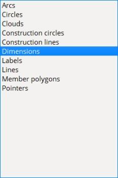
. An option is listed in the tree only if that option is checked
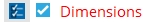
since the display filters are irrelevant when an option is not checked. To access the display filters for a particular option, select that option in the tree. Only one option at a time can be selected in the tree. When display filters for an option are non-default, that option turns red.
An alert symbol is also shown in the tree.Pressing the option's

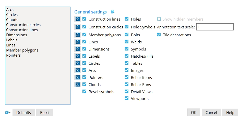
General settings
If this box
If the box
is not checked, construction lines are hidden.
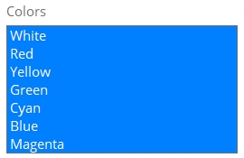
Display filters set the Pen color(s) of construction lines that are shown when
Clicking the Select All buttonresets the Construction lines display filters to their default state and changes the option name from red to black.
If this box
If the box
Display filters set the Pen color(s) of construction circles that are shown when
Clicking the Select All button
|
Note: This applies to erection views with members drawn as solid or stick + solid or wire. It does not affect stick members.
If this box
If the box
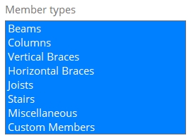
Display filters set the member types that are shown when
Clicking the Select All button
If this box
If the box
Display filters set the Pen color(s) and Line type(s) of lines that are shown when
Clicking the Select All button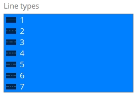
Note: This applies to linear dimensions, arc dimensions, extension dimensions, and angle dimensions.
If this box
If the box
Display filters set the Pen color(s) and Dimension type(s) that are shown when
Clicking the Select All button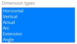

If this box
If the box
Display filters set the Pen color(s) of labels that are shown when
Clicking the Select All button
If this box
If the box
Display filters set the Pen color(s) and Line type(s) of circles that are shown when
Clicking the Select All button
If this box
If the box
Display filters set the Pen color(s) and Line type(s) of circles that are shown when
Clicking the Select All button
If this box
If the box
Display filters set the Pen color(s) of pointers that are shown when
Clicking the Select All button
If this box
If the box
Display filters set the Pen color(s) and Line type(s) of clouds that are shown when
Clicking the Select All button
If this box
If the box
If this box
If the box
If this box
If the box
If this box
If the box
If this box
If the box
If this box
If the box
If this box
If the box
If this box
If the box
If this box
If the box
If this box
If the box
If this box
If the box
If this box
If the box
If this box
If the box
Note: This applies when your current drawing is an erection view. Entire members can be hidden by selecting Hide for Show vertical braces that are not in this plane or Show horizontal braces that are not in this plane when you Detail Erection Views. Individual member lines and marks can be hidden using Evu Cleanup tools. Members are also hidden when you choose to
If this box
If the box
Annotation text scale: The scale of the point location annotation text. This scale applies to the dimension that is shown when you locate a second point with ANNO turned on. The scale also applies to the text that identifies the operative snap mode.
Example: A scale of 1 is the default. If you double the scale, the text will be twice as high and twice as wide. Be aware that the text always stays this same size, regardless of how much you zoom in or zoom out.
|
From left to right, the tile decorations in this example are Toggle Active Tile, Split Tile Vertically, Split Tile Horizontally, Single Tile, and Four Tiles. |
If this box
If the box
Setting the default: User and Site Options > General > Tile decorations active sets the default selection that will be made here when you first launch the Drawing Editor. If you make a change here, your change will remain in effect as you open different drawings, until you exit the Drawing Editor.
Buttons
 Forms
Forms

|
|
OK (or the Enter key) saves the changes you made and closes this window.
Cancel (or the Esc key) closes the window without saving any of the changes you made.
Reset undoes all changes made since you first opened Display Options.

