 Point Location Configuration ( Modeling & Drawing Editor )
Tool summary :
The Point Location Configuration window :
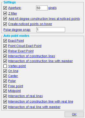
" Settings " are always visible, and can be changed, even when you are not using a tool that requires point location.
" Auto point modes " are packed (visible) only if you are using a tool that enables Locate options (for example, Construction Line Add ).
To open this window:
▸ Click the Point Location Configuration icon, which is pictured above. The icon can be found in the group named ' Locate ' and can be placed on the ribbon.
▸ Point Location Configuration can also be configured to be invoked using a keyboard shortcut , the context menu , or a mode . For the lightning interface, this configuration is done using Customize Interface .
Also see :
- Modeling and the Drawing Editor (where this window can be found)
- Auto (this window is setup for)
- Drag and Drop Configuration (a similar window, Drawing Editor )
- Locate options (must be active to set " Auto point modes ")
- X-Y-Z display (feedback for point location)
- Depth checking limits (set which points are available for location)
Aperture: ![]() (plus a distance in pixels ) or
(plus a distance in pixels ) or ![]() . Definition : Locatable points are those points whose icons are selected when Auto is active (when its icon is gray). Special application : The " Aperture " entered here also applies in Select Items mode (whether this box is checked or not checked) when you stretch a dimension by its line, tail or leg, or when you move a construction line or construction circle.
. Definition : Locatable points are those points whose icons are selected when Auto is active (when its icon is gray). Special application : The " Aperture " entered here also applies in Select Items mode (whether this box is checked or not checked) when you stretch a dimension by its line, tail or leg, or when you move a construction line or construction circle.
If this box is checked (
), you can enter the distance (in pixels) from the mouse pointer (
) that Auto will search within for locatable points. If Auto is configured to add the functionality of Free Point , you can locate a free point whenever the mouse pointer is positioned more than this number of pixels away from the nearest locatable point. If Auto is not configured to add the functionality of Free Point but is configured to add the functionality of Center of Screen , a point will be placed at the center of the drawing file or view when the mouse pointer is positioned more than this number of pixels away from the nearest locatable point. The " Aperture " also affects dragging certain types of objects in Select Items mode; more specifically, it sets the distance the mouse pointer must be to a Drag and Drop Configuration point in order for the dimension leg, construction line or construction circle being dragged to snap to that point.
If the box is not checked (
), then Auto will search the entire drawing file or view (within the limitations of depth checking ) for the nearest locatable point.
Locatable points: When Auto is active (when its icon is gray ), locatable points are those points whose boxes are checked under Auto point modes . On your ribbon, these same locatable points can be identified by those Locate icons which are highlighted in gray .
If this box is checked (
If the box is not checked (
Tip: When the " Z filter " widget is checked (
Add 45 degree construction lines at noticed points: ![]() or
or ![]() .
.
If this box is checked (
If the box is not checked (
Tip: A " Toggle ... " icon can be used to check/uncheck the " Add 45 degree ... " check box without your having to open this window.
Create noticed points on hover: ![]() or
or ![]() .
.
|
If this box is checked (
) with your mouse pointer (
If the box is not checked (
As mentioned above, turning this option off does not turn off construction lines through the first point that is located during an operation. It only affects the noticed points that are generated by hovering.
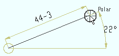
Polar degree snap: A number of degrees . Polar Point can be used for locating a second point. When Polar Point is the active Locate option, non-horizontal movement of the target ( ![]() ) is governed by the number of degrees of vertical offset that your mouse pointer (
) is governed by the number of degrees of vertical offset that your mouse pointer ( ![]() ) is from to 0° snap. The 0° snap is horizontal across your computer screen from the first point that you located. " Polar degree snap " sets the rotational increments the target will snap to when your mouse pointer is positioned an arbitrary number of degrees from the 0° snap.
) is from to 0° snap. The 0° snap is horizontal across your computer screen from the first point that you located. " Polar degree snap " sets the rotational increments the target will snap to when your mouse pointer is positioned an arbitrary number of degrees from the 0° snap.
|
For this example of Polar Point , the " Polar degree snap " might have been 22, 11, 2 or 1 degree. Most likely, the snap is a small increment such as ' 1 ' or ' 2 ', since the mouse pointer and target are so close. |
To test how this works, try Polar Point using a small " Polar degree snap " such as ' 1 ' degree. Then try it again, using a large " Polar degree snap " such as ' 45 ' degrees. With the small snap, the point location target (
Example 1: You enter ' 1 ' as the " Polar degree snap ." As you rotate around the first point that you locate, Polar Point snaps to points at 1 degree increments (0, 1, 2, 3, 4, 5, etc.).
Example 2: You enter ' 5 ' as the " Polar degree snap ." As you rotate around the first point that you locate, Polar Point snaps to points at 5 degree increments (0, 5, 10, 15, 20, 25, etc.).
Example 3: You enter ' 10 ' as the " Polar degree snap ." As you rotate around the first point that you locate, Polar Point snaps to points at 10 degree increments (0, 10, 20, 30, 40, 50, etc.).
------ Auto point modes ------
- Auto settings are configurable by tool. You can, for example, set up a different point locators for Construction Line Add and Construction Circle Add .
- These settings are disabled (grayed out) when you are not in a tool. To set " Auto point modes ," you need to first start up the tool for which you want them to be set. For example, invoke Construction Line Add .
-
removes that point locator from Auto for the particular tool you are using.
Exact point adds EXPT to Auto for the particular tool you are using.
Point cloud exact point adds PCEXPT to Auto for the particular tool you are using.
Rebar exact point adds REP to Auto for the particular tool you are using.
Intersection of construction lines adds INCL to Auto for the particular tool you are using.
Intersection of construction line with member adds INCM to Auto for the particular tool you are using.
Vertex point adds VTPT to Auto for the particular tool you are using.
On line adds On Line to Auto for the particular tool you are using.
Center adds CNTR to Auto for the particular tool you are using. Auto finds the center of the screen only if FRPT is not active and no other locatable point is closer to the mouse pointer ( ) than the " Aperture ."
Polar adds Polar to Auto for the particular tool you are using. The " Polar degree snap " controls the sensitivity of Polar to movement of the mouse pointer ( ).
Free point adds FRPT to Auto for the particular tool you are using. Auto lets you locate a free point wherever no other locatable point is closer to the mouse pointer than the " Aperture ."
Midpoint adds MDPT to Auto for the particular tool you are using. May be used in the Drawing Editor or in Modeling .
Intersection of real lines adds INRL to Auto for the particular tool you are using. Snaps to the midpoint of a line, polygon side, member line or, in Modeling , a member workline. Also may be used with REFD in Modeling .
Intersection of construction line with real line adds INCR to Auto for the particular tool you are using. May be used in the Drawing Editor or in Modeling with REFD .
Intersection of real line with member adds INRM to Auto for the particular tool you are using. May be used in Modeling with REFD .
![]() To close this window :
To close this window :
"OK" closes this window. You do not have to close this window to apply the settings on it.
Note: The settings on this window remain in effect even after you Exit and restart the Drawing Editor or Exit and restart Modeling .

