 Add Hole Window and Command
Default Shortcut: h + h
Locate a point on a surface of a material to add a hole or hole group to that material.
Before using this tool, use Snap to Surface or a related tool to go to a plane that is parallel with the surface of the material to which you want to add the hole group.
- General Overview
- Step-By-Step
- Tips and Tricks
- Related Tools
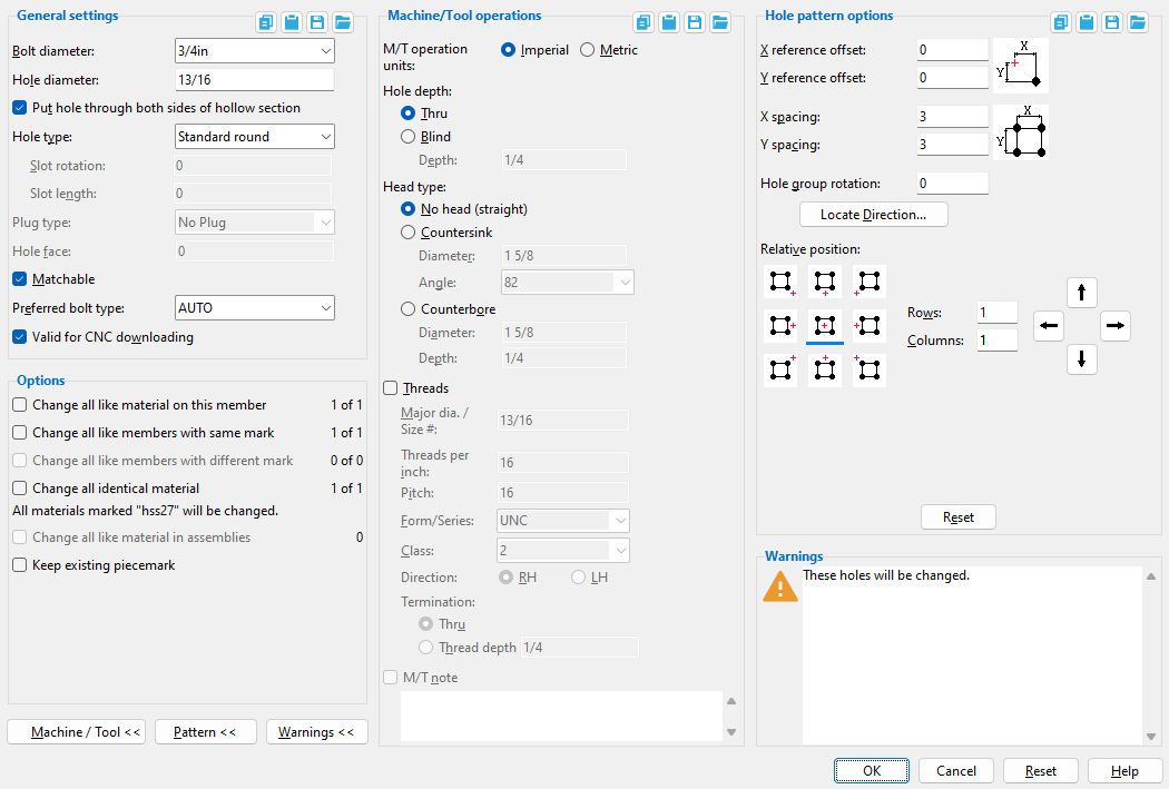
 General settings " and all " Machine / Tool operations " are also available on the Hole Edit window ( Modeling ) and the Hole Edit window ( Drawing Editor ). Be aware that a hole needs to be edited in Modeling if you want your changes to be CNC downloaded. Changes made to a hole in the Drawing Editor affect drawings only -- they do not affect CNC.
------ General Settings ------
Bolt diameter: The diameter of the shanks of the bolts to be inserted into the holes you are adding.
To make an entry: You can either type in any diameter (inches or mm), or you can select a bolt diameter from the combo box (
). The diameters that are listed in the combo box come from Home > Project Settings > Job > Bolt Settings > the " Available bolts " list.
Effect on Modeling: From the diameter entered here and the " Hole type ," connection design calculates the required " Hole diameter " per Table J3.3 or Table J3.3M ( AISC Thirteenth Edition , p. 16.1-105). If the " Hole type " is ' User slot #1 ' or ' User slot #2 ', the system-calculated slot length comes from Home > Project Settings > Job > User Slot Lengths .
Note: The default bolt diameter is the non-moment " Bolt diameter " entered at Home > Project Settings > Job > Bolt Settings . If you change the " Bolt diameter " from this default then later add more holes, your last entry is used as the default. When you exit Modeling and return, the default is set back to the " Bolt diameter " from setup.
Hole diameter: A system-calculated or user-entered distance. On a ' Standard Round ' hole, the calculated value will typically be 1/16" larger than the input " Bolt diameter ."
To add a CNC mark: Enter a diameter of ' 0 ' (zero). An "X" is used to represent a CNC mark in a view (or, for that matter, on a detail drawing).
 .
.
Note: The default " Hole diameter " is typically 1/16 inch larger than the default " Bolt diameter " entered at Home > Project Settings > Job > Bolt Settings , unless you previously added a hole with a different diameter during this session in Modeling -- in which case the default will be the last hole added.
Put hole through both sides of hollow section:
![]() or
or ![]() . This is an option only if you are adding holes to hollow sections ( HSS round or HSS rectangular material).
. This is an option only if you are adding holes to hollow sections ( HSS round or HSS rectangular material).
If this box is checked (
), the pattern of holes shown on screen will be duplicated through the opposite wall of the material (which you cannot see right now).
If the box is not checked (
), the pattern of holes shown on screen will be added only to the surface on which they are shown right now.
Hole type: Standard round or Short slot or Oversized round or Long slot or Cope hole or Erection pin hole or Anchor bolt hole or Plug weld hole or Grout or User slot #1 or User slot #2 .
A ' Standard round ' hole is perfectly round and has a " Hole diameter " that is typically 1/16 inch larger than the " Bolt diameter ." See Table J3.3 or Table J3.3M ( AISC Thirteenth Edition , p. 16.1-105).
A ' Short slot ' hole is oblong in shape and has a relatively short " Slot length " (1 5/16 inch for a 1 inch diameter bolt).
An ' Oversized ' hole will typically input a " Hole diameter " 3/16 inch larger than the " Bolt diameter ."
A ' Long slot ' hole is oblong in shape, has a diameter 1/16 inch larger than the input bolt diameter, and has a relatively long " Slot length " (2 1/2 inch for a 1 inch diameter bolt).
A ' Cope hole ' is for using a punch or drilling machine instead of a cutting machine to cope a piece of material. By default, cope holes are not matchable ("
An ' Erection pin hole ' is a hole on the end of a column for use by a crane to lift the column into place (see show erection pin holes on columns ). By default, erection pin holes are set to be not matchable ("
An ' Anchor bolt hole ' is a hole for anchor bolts in a column base plate. Holes must be of this type in order for them to be automatically dimensioned when the " Dimension anchor bolt layout " option is selected during erection view regeneration. By default, anchor bolt holes are not matchable ("
A ' Plug weld hole ' is for adding to a material before the material is plug welded . By default, plug weld holes are not matchable ("
A ' Grout ' hole may be used for pouring grout under a base plate. By default, vent/drain holes are not matchable ("
' User slot #1 ' and ' User slot #2 ' are slots whose " Slot length " are set, based on the " Bolt diameter ," from user-entered length settings maintained at Home > Project Settings > Job > User Slot Lengths .
Slot rotation: A positive or negative value from 90 to -90 degrees. This field only applies to ' Long slot ' and ' Short slot ' " Hole types ." Slot rotations can be modeled to a precision of 0.1 degree.
| <= hole group X axis => |
|
|
An entry of ' 0 ' (zero) degrees sets the length of the slot parallel with the hole group X axis .
A ' positive number ' of degrees rotates the slot counterclockwise that number of degrees.
A ' negative number ' of degrees rotates the slot clockwise.
Slot length: The system-calculated or user-entered distance (in the primary dimension " Units " or other units ) between the two points farthest from one another on the perimeter of a slot. This field only applies when ' Long slot ' or ' Short slot ' is selected as the " Hole type ."

An ' system-calculated slot length ' is the standard slot length based on the " Bolt diameter " and " Hole type " per Table J3.3 or Table J3.3M ( AISC Thirteenth Edition , p. 16.1-105).If the " Hole type " is ' User slot #1 ' or ' User slot #2 ', the calculated slot length comes from Home > Project Settings > Job > User Slot Lengths .
A ' user-entered slot length ' must be entered after the " Hole type " has been established. If you have entered a distance here and want to replace that distance with the standard slot length, simply go back and select the " Hole type " that you want again.
Plug type: No Plug or Zinc Plug or Plug Weld or Aluminum or Epoxy . This applies when the " Hole type " is ' Cope hole ', ' Plug weld hole ', ' Grout ', or ' Vent/Drain '.
' No Plug ' should be selected if there is no reason for plugging the vent/drain hole.
' Zinc Plug ' or ' Plug Weld ' or ' Aluminum ' or ' Epoxy ' are various types of plugs or methods for plugging vent/drain holes after galvanizing in order to seal the hole and smooth the surface of the material.
Status Display: Hole status > Plug type
Hole face: The face of the material the hole is to be drilled or punched from. The faces of different materials are described as illustrated below.
Application: You might want to change the face, for instance, to put the holes on the opposite face (for the purposes of CNC downloading) so that they will be drilled from a direction opposite to the direction they were originally placed.
If this box is checked (
If the box is not checked (
Note: Certain " Hole types " are, by default, set to not matchable ("
Preferred bolt type: Auto or A325N or etc.
If ' Auto ' is selected, the non-moment " Bolt type " from Bolt Settings is used to determine the bolt type when bolts are added to this hole.
Selecting ' a specific bolt type ' overrides the choice you have made to Bolt Settings . If the type of bolt you want is not listed in the list box (
Valid for CNC downloading:
![]() or
or ![]() .
.
If this box is checked (
If the box is not checked (
------ Machine/Tool Operations ------
| Please note: For these options to be enabled, the " Hole type " must be ' Standard round '. |
M/T operation units: ![]() Imperial or
Imperial or ![]() Metric .
Metric .
'
Imperial ' lets you make distance entries to fields in this section in the same way that you make distance entries everywhere else in SDS2. How you make distance entries primarily depends on the primary dimension " Units " that are specified in Home > Project Settings > Fabricator > Detailing > Drawing Presentation > the " Primary Dimensions " tab. Be aware, though, that you can still make entries in other units .
'
Hole depth: ![]() Thru or
Thru or ![]() Blind . The " Hole type " for a blind hole must be ' Standard round '.
Blind . The " Hole type " for a blind hole must be ' Standard round '.
|
'
'
VIDEO 
Hole information for a blind hole is shown on a legacy miscellaneous member detail. "Depth" is the length of the blind hole in the " M/T units ."
A blind hole's depth is the distance from the material's surface (the " Hole face ") to the bottom of the hole.
A label on a member detail indicating that the depth of a blind hole is 0.75 inch.
Head type: ![]() No head (straight) or
No head (straight) or ![]() Countersink or
Countersink or ![]() Counterbore . The " Hole type " for a countersink or counterbore hole must be ' Standard round '.
Counterbore . The " Hole type " for a countersink or counterbore hole must be ' Standard round '.
|
'
'
VIDEO The label for a countersink hole with threads is shown on the member detail.
A label on a member detail that calls out a 0.81 inch hole with a countersink diameter of 1.63 inch and an angle of 82 degrees. "Diameter" is the countersink hole's maximum diameter (in the " M/T units ").. The hole is at its maximum diameter at the surface of the material.
|
The diameter of the hole at the end opposite to the countersink is the " Hole diameter " or, if the hole is threaded, the " Major dia ." |
"Angle" is the angle of the countersink (in degrees). This is the angle between opposite sides of the countersink conical bore. You can enter any number of degrees that you like, or you can select a value from the combo box menu.
|
The specified " Angle " (' 90 ' in this example) sets the angle between opposite sides of the countersink cone. |
'
VIDEO Hole information for a counterbore hole is shown on a legacy miscellaneous member detail.
A counterbore is defined by its " Diameter " and a " Depth ."
A label on a member detail that calls out a 0.81 inch hole with a counterbore diameter of 1.63 inch and a counterbore depth of 0.25 inch. "Diameter" is the counterbore diameter (in the " M/T units ") at the " Hole face " surface of the material.
"Depth" is the length of the counterbore (in the " M/T units "). This distance is from the material's surface (the " Hole face ") to the bottom of the counterbore.
Threads:
![]() or
or ![]() . The " Hole type " for a hole with threads must be ' Standard round '. The hole can be a blind hole or thru hole or have any " Head type ."
. The " Hole type " for a hole with threads must be ' Standard round '. The hole can be a blind hole or thru hole or have any " Head type ."
|
Most thread information is not modeled, but the thread information does affect the hole symbol callout label that may be generated during auto detailing or when you use the Add Material Callout tool. |
If this box is checked (
If the box is not checked (
Major dia. / Size #: The nominal diameter of the threaded hole. This is the threaded portion of a hole's largest diameter or outside diameter. By default, the major diameter is the same as the " Hole diameter ." " Major dia. " affects the hole symbol callout label for a threaded hole.
When " M/T units " is ' Imperial ', a diameter symbol ø precedes the major diameter value, which is expressed in decimal inches.
|
ø.81 = " Major dia. " (inch) 16 = " Threads per inch " UNC = " Form / Series " 2 = " Class " RH = " Direction " |
When " M/T units " is ' Metric ', the letter M precedes the major diameter, which is expressed in millimeters. In the example below, the major diameter is 21 mm.
|
M21 = " Major dia. " (mm)
1.588 = " Pitch " 5H/5g = " Class " |
Threads per inch: This is the count of the threads per inch (TPI) along the depth of the hole. This applies when " M/T units " is ' Imperial '. If you change the " M/T units " to ' Metric ', the name of this field will be changed to " Pitch " and the TPI value you entered will be converted to pitch. " Threads per inch " affects the hole symbol callout label for a threaded hole. TPI does not affect the representation of a hole in Modeling .
|
|
ø.81 = " Major dia. " (inch) 16 = " Threads per inch " UNC = " Form / Series " 2 = " Class " RH = " Direction " |
| Threads per inch (TPI) is the inverse of " Pitch ." For example, if the threads per inch are 32, then 1/32 (the inverse) = 0.03125 inch. Converting this to mm gives you: 0. 0.031250 inch x 25.4 mm/inch = 0.79375 mm. Thus, in a standard table of screw threads, a TPI of 32 is equal to a pitch of 0.7938 mm. |
Pitch: The distance between thread peaks in millimeters. Pitch is the inverse of threads per inch, but expressed in mm: In other words, pitch is millimeters per thread. " Pitch " is available as an entry field when the " M/T units " is ' Metric '. The pitch value that you enter here is recorded in the hole symbol callout label for a threaded hole. Pitch does not affect the representation of a hole in Modeling .
|
|
M21 = " Major dia. " (mm)
1.588 = " Pitch " 5H/5g = " Class " |
Form / Series:None or UNC (coarse) or UNF (fine) or UNEF (extra fine).. This applies when " M/T units " is 'Imperial ' and " ![]() Threads " is checked. It affects the hole symbol callout label for a threaded hole. In the example below, the series is UNC (coarse).
Threads " is checked. It affects the hole symbol callout label for a threaded hole. In the example below, the series is UNC (coarse).
|
|
ø.81 = " Major dia. " (inch) 16 = " Threads per inch " UNC = " Form / Series " 2 = " Class " RH = " Direction " |
' None ' results in the form / series not being included in the hole callout label. If ' None ' had been selected for the above example, the label would read: ø.81-16-2B-RH .
' UNC ' stands for Unified National Course. For the example above. ' UNC ' was selected as the "Form / Series," and therefore the label reads ø.81-16UNC-2B-RH .
' UNF ' stands for Unified National Fine. If 'UNF' had been selected for the example above, the label would read ø.81-16UNF-2B-RH .
' UNEF ' stand for Unified National Extra Fine. For the example above. ' UNEF ' was selected as the " Form / Series ," and therefore the label reads ø.81-16UNC-2B-RH ,
Class:1 or 2 or 3 or 6H/6g or etc. " Class " is a designation of tolerance, or the closeness of fit between two mating parts. You can type in any class you like, or you can select a class from the combo box menu. The class you specify is recorded to the thread information line on the hole symbol callout label for a threaded hole. Class does not affect the representation of a hole in Modeling . In the example below, the class is 2, and B indicates that the thread is internal.
|
|
ø.81 = " Major dia. " (inch) 16 = " Threads per inch " UNC = " Form / Series " 2 = " Class " RH = " Direction " |
When " M/T units " is ' Imperial ':
' 1' indicates generous tolerance.' 2 ' designates normal production. If no class is designated, common practice is to assume that 2 is the class. .
' 3 ' designates high accuracy.
Note: The letter B in the imperial example shown above indicates internal thread, i.e., threads in a hole, the female part. A nut would also have internal threads. The letter A would indicate external threads, i.e., threads in a screw, the male part.
M21 = " Major dia. " (mm)
1.588 = " Pitch "
5H/5g = " Class "When " M/T units " is ' Metric ':
' 6H/6g ' indicates general purpose. If no class is designated, common practice is to assume that 6H/6g is the class.' 4H/4g ' and ' 5H/5g ' and ' 7H/7g ' are a few other selections that you can make to
As stated above, you can type almost any value you like to this combo box .
Direction: ![]() RH or
RH or ![]() LH . In the example below, the direction is RH (right-handed).
LH . In the example below, the direction is RH (right-handed).
|
|
ø.81 = " Major dia. " (inch) 16 = " Threads per inch " UNC = " Form / Series " 2 = " Class " RH = " Direction " |
'
'
Termination: ![]() Thru or
Thru or ![]() Thread depth .
Thread depth .
'
'
The " Depth " specified for this example is 0.5 inch. "Depth" is the length of the threads (in the " M/T units "). This distance is from the material's surface (the " Hole face ") to the depth of the hole at which you want the threads to end.
M/T note: Any text can be entered, including Latin 1 characters 0160 to 0255 . To enter special characters, hold down the Alt key and type in the number, or copy and paste from the Character Map that can be launched from your operating system's Accessories menu. To enter multiple lines, press the Enter key where you want a line break. The line(s) of text that you enter will appear below other lines in the hole symbol callout label for a M/T hole.
|
TYPICAL is the " M/T note " in this example of a hole callout label. |
------ Hole Pattern Options ------
| The following will appear (or go away) when you press the " Hole Pattern Options " button. Tip: You'll get better dimensioning results on the detail if you use these options instead of adding individual holes. Also see " Reset ." |
X reference offset: When the " Hole Group Rotation " is ' 0 ' degrees, this is the distance (in the primary dimension " Units " or other units ) along the X material axis from the hole group reference point to the first column of holes. Changing the " Hole Group Rotation " will change the axis along which this offset is measured.
Y reference offset: When the " Hole Group Rotation " is ' 0 ' degrees, this is the distance (in the primary dimension " Units " or other units ) along the Y material axis from the hole group reference point to the first column of holes. Changing the " Hole Group Rotation " will change the axis along which this offset is measured.
X spacing: The distance (in the primary dimension " Units " or other units ) between the centers of columns of holes in a hole group. If the " Hole Group Rotation " is ' 0 ' (the default), this distance is parallel with the X axis of the material that you are adding holes to. The X axis symbol shown on screen points in the direction of this spacing.
|
| The " X Spacing " changes in these illustrations. Other hole group settings remain the same. |
Y spacing: The distance (in the primary dimension " Units " or other units ) between rows of holes in a hole group. If the " Hole Group Rotation " is ' 0 ' (the default), this distance is parallel with the Y axis of the material that you are adding holes to. The Y axis symbol shown on screen points in the direction of this spacing.
|
| The " Y Spacing " changes in these illustrations . The other hole group settings remain the same. |
Hole group rotation: A positive or negative number of degrees ( 180 to -180 ).
' 0 ' (zero) degrees specifies that the hole group rotation is governed by the material axes of the submaterial you are adding the holes to.
A ' positive number ' of degrees will cause counterclockwise rotation of the hole group (and the hole group axes shown on screen).
A ' negative number ' of degrees will cause clockwise rotation of the hole group.
Note 1: The number of degrees that you set for the " Hole group rotation " affects the angle at which the " X reference offset " or " Y reference offset " is measured from the reference point.
Note 2: If the " Hole group rotation " on this window is ' 0 ' (zero), the X hole group axis will be parallel with the X material axis . If you change the " Hole group rotation " to something other than zero, the X hole group axis for the hole group you are adding will be rotated from its default position (and the default for subsequently added hole groups will then become the " Hole group rotation " you have entered).
"Locate Direction ..." lets you locate a second point with respect the reference point .
1 . The status line prompts, " Locate second point ."
2 . With the Locate option you want selected, move your mouse pointer (
) on screen so that the point location target (
) snaps to the point you want, then left-click ( Locate ).
3 . A value is automatically entered to " Hole group rotation ," and the outlines of the holes you are Adding are automatically repositioned. Right-click ( Return ) to accept the new rotation, or go back to step 2.
Relative position: Any one of nine buttons . The button that is pressed sets the orientation of a hole group with respect to its reference point . It's a good idea to watch on screen as you press these buttons -- Modeling shows you how the holes will be placed.
|
The " Hole group orientation " button that is pressed changes in these illustrations. The other settings are all the same. |
Rows: For a hole group whose Y axis is vertical (on a horizontal beam, the Y axis is vertical), this is the number of rows of holes in the hole group that are above or below the hole group reference point, or it is half the number of rows both above and below the hole group reference point, or it is the "special case" described below. Rows of holes align with the Y hole group axis .
Special case: When you have designated rows of holes for both above and below the reference point and have entered a " Y reference offset " of ' 0 ', the number of rows of holes you actually get will be twice the number entered here minus 1.
Note: How rows of holes are oriented with respect to the reference point (and also the number of holes you get) depends on the hole group orientation button that is pressed.
Columns: For a hole group whose X axis is horizontal (on a horizontal beam, the X axis is horizontal), this is the number of columns of holes in the hole group that are to the right or left of the hole group reference point, or it is half the number of columns both to the right and left of the hole group reference point, or it is the "special case" described below. Columns of holes align with the X hole group axis .
Special case: When you have designated columns of holes for both the left and right of the reference point and entered a " X reference offset " of ' 0 ', the number of columns of holes you will actually get will be twice the number entered here minus 1.
Note: How columns of holes are oriented with respect to the reference point (and also the number of holes you get) depends on the hole group orientation button that is pressed.
![]() resets the " Hole pattern options " back to the way they were when you first opened this window. Only the " Hole pattern options " are affected by this button.
resets the " Hole pattern options " back to the way they were when you first opened this window. Only the " Hole pattern options " are affected by this button.
Definition: " Like holes " are holes with the same settings (diameter, type, etc.) and in the same pattern with the same relative reference point as the holes you are adding.
Definition: " Like material " is material with the same submaterial piecemark as the material you are adding holes to. The material must be also be in the same relative position on the member (e.g. top flange verses bottom flange) as the material you are adding the holes to.
Definition: A " like member " is a member which has like material with the same submaterial piecemark as the material you are adding holes to.
Change all like material on this member:
![]() or
or ![]() . The count listed to the right of this field is the number of pieces of like material on this member only (including the material you are working on).
. The count listed to the right of this field is the number of pieces of like material on this member only (including the material you are working on).
If this box is checked (
Change all like members with same mark:
![]() or
or ![]() . The count listed for this field is the number of members that have the same mark as the member you are working on (including the member you are working on). If the member you're working on is the only member, this number will be 1.
. The count listed for this field is the number of members that have the same mark as the member you are working on (including the member you are working on). If the member you're working on is the only member, this number will be 1.
If this box is checked (
Change all like members with different mark:
![]() or
or ![]() . The count for this field is the number of members that exist in the 3D model that do not have the same piecemark as the member you are working on but do have like material . If no such members exist, then this number will be zero (0).
. The count for this field is the number of members that exist in the 3D model that do not have the same piecemark as the member you are working on but do have like material . If no such members exist, then this number will be zero (0).
If this box is checked (
Change all identical material:
![]() or
or ![]() . The count for this field is expressed in the form " x of y ," where " x " is the number of materials that will be operated on and " y " is the total number of those same materials. The indented line beneath this line tells you the submaterial mark of the materials that will be changed.
. The count for this field is expressed in the form " x of y ," where " x " is the number of materials that will be operated on and " y " is the total number of those same materials. The indented line beneath this line tells you the submaterial mark of the materials that will be changed.
If this box is checked (
Change all like material in assemblies:
![]() or
or ![]() . The count for this field is the number of pieces of like material that exist in the 3D model and that were originally added to the model by Adding an assembly.
. The count for this field is the number of pieces of like material that exist in the 3D model and that were originally added to the model by Adding an assembly.
If this box is checked (
If this box is checked (
If the box is not checked (
------ Warnings ------
| The following warnings ( "in quotes" ) may appear when you press the " Warnings " button. They tell you the consequences of pressing " OK " on this window. If you press " Cancel ," the warnings do not apply. |
" Hole Add Will Fail: Attempt to add hole off of the material " indicates that at least one of the holes you are adding is not on the material. You may be able to fix this problem by making changes to the " Hole pattern options ." When you fix the problem, this warning will go away.
" Connection will be changed to a Graphical User connection " indicates that the material you are adding holes to is currently part of a system connection . The connection will be changed to a graphical user connection , which means that it will not be altered during Process and Create Solids . When a member has a graphical connection on either its right or left end, the " Connection " for that end is marked as "

" This member will need to be redetailed " indicates that adding the hole group to the material will cause the associated member(s) listed next to this message to need to be redetailed. All affected members are marked for detailing when you press " OK ." On the edit windows of the affected members, " Marked for detailing " will be set to ' YES ' (
).
" Detail drawing marked as completed. Member will not be redetailed " indicates that the detail complete flag is on for the affected member (which means it can't be redetailed). You will need to turn the detail complete flag off if you want to redetail.
" This member will need to be reprinted " indicates that you have printed the detail for the member you are adding this hole to.
" This member is approved. Approval status will be reset " tells you that when you press " OK ," the " Submitted for approval " status of the affected members will be changed back to ' ***NOT SET*** '.
" This member has been released for fabrication " indicates that a " Released for fabrication " date has been set.
" This member has been fabricated " indicates that a " Fabrication completed " date has been set.
"OK" (or the Enter key) closes this window and adds hole(s) per its settings.
For further instructions, see step 6 .
"Cancel" (or the Esc key or the ![]() button) closes the window and ends the Add Hole operation.
button) closes the window and ends the Add Hole operation.
"Reset" undoes all changes made to this window since you first opened it. The window remains open.
Tip: It you want to reset the hole pattern only, there is another " Reset " button under " Hole pattern options ."
1 . Invoke Add Hole using one (1) of the following methods:
▸ Click the Add Hole icon, which is pictured above. The icon can be found on the Material page > Holes section. Proceed to step 2.
▸ Preselect a material you want to add a hole or hole group to. This enables the Materials contextual page. Click the Add Hole icon found in the Holes section. Skip step 2.
Alternative: Invoke Add Hole using the Find Tool by searching the command name and clicking the Add Hole icon, which is pictured above. Proceed to step 2.
Learn more about alternative methods for launching commands.
2 . Select the material you want to add a hole or hole group to.
3 . The Locate options become active along with Locate - Repeat - Return mouse bindings. The status line prompts, "Add: Holes"
Option 1 : With the appropriate Locate icon selected, place your mouse pointer (
( Locate ). Individual holes placed with Repeat may be dimensioned more tightly to the hole group than are holes placed with Locate .
Option 2 : Right-click Return to cancel the command.
4 . The Hole Add window opens. A hole reference point symbol with arrows (hole group axes) labeled "X" and "Y" point from the reference point (located in step 4) in positive directions along the material's X & Y axes . Changing the " Hole group rotation " on the Hole Add window changes the orientation of these hole group axes.
4a : On the Hole Add window, enter the " General Settings " first, then the " Hole Pattern Options ." Note that outlines of holes are shown on screen in the pattern you are adding. Also note the " Reset " button for resetting hole patterns.
4b : Press the " OK " button when you are done entering hole group settings to the window.
5 . The outlines of holes in the hole group you just added are displayed on the material. Locate - Repeat - Return mouse bindings become active. Do one of the following:
Alternative 1 : If you want to place another hole group similar to the one you just added, move your mouse pointer (
Alternative 2 : If you want to place another hole group exactly like the one you just added, move your mouse pointer to the appropriate location and middle-click ( Repeat ).
Alternative 3 : When you have finished adding holes, right-click ( Return ). Go to step 6.
6 . The status line prompts, "Verify hole group reference location and direction" Yes-No mouse bindings become active.
Alternative 1 : Left-click ( Yes ) to keep both the reference point and direction as shown on screen and end the command.
Alternative 2 : Right-click ( No ) if you want to change either the reference point location or direction. For more information about changing the hole group reference point and direction, please refer to Hole - Set Reference Point.
- Hole Match
- Hole Edit
- Hole Edit window
- Hole Erase
- Hole Move
- Hole Group Move
- Hole - Set Reference Point
- Hole Properties
- 3D holes (about holes in Modeling)
- Important information about 3D holes (topic)
- Selection filter
- Default non-moment bolt diameter (sets default hole size)

