Add Horizontal Brace ( Modeling > F2 >   Structural Steel > select " Horz Brc ")

VIDEO A double-angle horizontal brace is added in a plan view . View > Relative Depth is used to adjust the work plane of that plan view so that INCL points snap to a lower elevation. (Recorded in SDS2 Detailing , v7.2.)

Tool summary :

  • Adds a horizontal brace to the 3D model. Locate two points and make entries to the Horizontal Brace Edit window to define the brace.
  • To get a new horizontal brace that is similar to one that was previously added, double-click the previously added brace and press " OK " on its edit window without changing anything. Then Add Horizontal Brace .
  • See (on this page):

Also see :

Connection failure messages resulting from an improperly added brace :

page 1 | contents | F2 > structural steel > horizontal brace | top


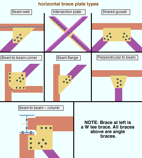
   Examples (horizontal brace framing situations) :

Shown below are some examples of different types of horizontal brace connections. The type of horizontal brace connection you get depends on where work points are located when the horizontal brace is added. Connection design can automatically create connections for horizontal braces framing to wide flange , channel , welded plate wide flange , S shape or HSS/TS beams.

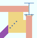
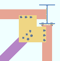
In the examples below, the work point " End elevation " determines whether the gusset plate fastens with clip angles to the webs of the beams (left) or bolts to the beam flanges (right). You can adjust the " End elevation " on the Horizontal Brace Edit window for a non-sloping horizontal brace. Be sure to lower/raise the elevation by exactly the same distance for both ends of the brace. Don't try this on a sloping brace.

brace below flange
brace at flange level

page 1 | contents | F2 > structural steel > horizontal brace | top


   Step-by-step instructions :

Horizontal braces have gusset plates that are in the same plane as the supporting beams the brace frames to. Connection design requires that horizontal braces be perfectly horizontal or slope up to 30 degrees from horizontal. In most cases, a horizontal brace that is sloping must be in the same plane as the beam that it frames to, which means that for a roof that slopes 20 degrees, the brace must slope 20 degrees. A special case is a brace to two beams with or without an interposed column -- in this special case, bent plates can be designed to the web of the one beam that is not in the same plane as the brace. Two work points are required to lay out the work line of a horizontal brace. The following instructions assume that you are using a 3-button mouse.

1 . Before using this tool:

1a : For a non-sloping horizontal brace, open a plan view that is approximately at the elevation where you want the top of the horizontal brace. You can later adjust left & right " End elevation " on the Horizontal Brace Edit window if you want to lower the elevation of the horizontal brace.

1b : For a sloping horizontal brace, create a view whose work plane is parallel with the top flanges of the beams that the horizontal brace frames to. To do this, invoke Snap to Surface and click the top flange of one of the beams, then enter a negative Relative Depth to get below the flange of the beam.

1c : Lay out grid lines or construction lines so that there are points of intersection ( INCL points) wherever you want to place the work points of the horizontal brace(s) you are adding.

1d : Optionally set the toolbar icon or set User and Site Options > Modeling > " Automatically process after modeling operation " to a choice that will cause the horizontal brace you are adding to automatically have solids created and piecemarks applied when you press " OK " to close the Horizontal Brace Edit window that opens in step 4.

2 . Invoke Add Horizontal Brace using any one (1) of the following methods:

  • Right-click ( Menu ) and choose Add Member > Structural Steel > Horizontal Brace .
  • On your ribbon, click the Add Horizontal Brace icon that is pictured above. If the icon is not currently on the ribbon, you can add it using the Ribbon Editor . In the Ribbon Editor , choose Model -- Member > Add Horizontal Brace .
  • Use a keyboard shortcut (for example, F2 ). Add Horizontal Brace is in the keyboard configuration " Command group " called ' Model -- Member '.
  • With Member Mode mouse bindings active, middle-click ( Add ). On the selection dialog that opens, double-click " Horizontal Brace. "
  • You can also add the tool to a mode of your choice. In Mode Configuration , the tool can be selected from the " Command group " called ' Model -- Member '.

3 . Locators become active along with Locate - Repeat - Return mouse bindings. Locate two work points in the following manner:

bindings

3a : Select a Locate option (e.g. INCL ), then move your mouse pointer ( ) so that the point location target ( ) snaps to the beam (or beam to beam - column juncture) you want to frame to, then left-click ( Locate ).

3b : The status line prompts, " Locate second point:" Move the point location target ( ) to the beam (or beam to beam - column juncture) you want the other end of the horizontal brace to frame to, then left-click ( Locate ). Please note the following before going on to step 4:

Note 1: Together these two work points define the work line of the brace, the members the brace frames to, and the elevation of the brace (top flange for a WT or ST or wide flange or S shape brace; neutral axis for a HSS round or HSS rectangular brace; leg to gusset for an L brace).

Note 2: For a beam to beam - column juncture, you need to locate the horizontal brace work point at the workline (center) of the column.

Note 3: When the gusset bolts to the top/bottom flange of a beam, the work point can be located anywhere on the top/bottom flange.

Note 4: Connection design supports automatic connections on horizontal braces in X, K and W configurations. It used to be that you would get the failure message " Invalid shared brace configuration " if the middle brace of a 3-point brace was not perpendicular to the supporting member. That restriction no longer applies.

Note 5: When locating work points, look at the X-Y-Z Display -- for a non-sloping angle or tee horizontal brace, the Z coordinate tells you the elevation of the brace surface that fastens to the gusset. For a HSS/TS or pipe horizontal brace, the Z coordinate is the brace's neutral axis.

Note 6: Connection design cannot create a horizontal brace gusset plate on a brace with a slope of greater than 30 degrees. The brace must be in the same plane as the beam (for a roof that slopes 20 degrees, the brace must slope 20 degrees).

4 . The Horizontal Brace Edit window opens. On it are the settings of the horizontal brace whose work points you located in step 3 . Since process on the fly takes place even before the window opens, all relevant connection design locks are available to you immediately after the window opens, and process on the fly will continuously update connection design locks as you make changes on the edit window.

Alternative 1 : Edit the settings as desired (see the notes below), then press the " OK " button. Go to step 5.

Alternative 2 : Press the " Cancel " button to close this window and go back to step 3.

Note 1: Be sure that if two or three braces frame together to a shared gusset plate that you enter compatible material types for all of the braces.

Note 2: L , W , S , WT , ST , HSS round and HSS rectangular are acceptable section sizes for which connection design is able to generate connections on horizontal braces.

Note 3: The default settings on the Horizontal Brace Edit window are those of the last horizontal brace added or edited in this session of Modeling . Even if you just double-click a horizontal brace and press " OK " on its edit window, that brace's settings become the defaults for the next-added horizontal brace (exception: see " Swap member ends "). You therefore only have to make changes to those settings which are different for this horizontal brace.

Note 4: You can adjust the " End elevation " on this window for a non-sloping horizontal brace. Be sure to lower/raise the elevation by exactly the same distance for both ends of the brace. Don't try this on a sloping brace.

5 . The horizontal brace appears on your computer screen. Locate - Repeat - Return mouse bindings become active. If User and Site Options > Modeling > " Automatically process after modeling operation " is ' Process and create solids ', the new horizontal brace will have automatically undergone all phases of Process and Create Solids . If that option is ' Process ' or ' Do nothing ', then you will have to Process > Process and Create Solids in order to have the member piecemarked and able to be displayed in a solid form . Do one (1) of the following:

bindings

Alternative 1 : Move the mouse pointer ( ) and middle-click ( Repeat ) to add a new horizontal brace just like the one you just added from the point where the point location target ( ) is at. The X, Y and Z global axes location of the repeated brace will begin from the located repeat point (where the target is at). This means that if the Z coordinate of the repeated brace is different than the originat brace's " End elevation ," the repeated brace's end elevation will be different. The brace's other settings will be that of the last-added or last-edited horizontal brace.

Alternative 2 : Follow these instructions beginning at step 3 to add a horizontal brace with different settings.

Alternative 3 : Right-click ( Return ) if you are done adding horizontal braces.

Note: The stick representation of the brace includes a member orientation indicator showing the brace orientation.

The stem of this W tee brace points away from you.

The toe of this angle brace points away from you. 

page 1 | contents | F2 > structural steel > horizontal brace | top


   Adding horizontal braces using the options bar (classic) :

User and Site Options > Modeling > " Show member add options bar " can be set to ' Disabled ' or ' Top ' or ' Bottom '. When ' Top ' or ' Bottom ' is selected, extra space is allocated on your top or bottom toolbar to provide feedback and options related to the adding of a beam, column or brace. When you choose Model > Member > Add > Horizontal Brace or invoke Add Horizontal Brace using any other method , the options bar is activated, allowing you to quickly add horizontal braces without having to open the Horizontal Brace Edit window. Note in the following example that the left " End elevation " and right " End elevation " are unlocked ( ), which results in the elevation of the member ends being determined by the located points. Also, " User defined connection ") is disabled ( grayed out ) due to the " Input connection type " being set to ' Hbrc plate ' instead of ' User defined '.

The " Continuous add mode " button ( or ) stops and starts continuous mode. Horizontal braces added using continuous mode are end-to-end, with the second point of a just-added horizontal brace the same as the first point of the next-added horizontal brace. Continuous mode requires the location of fewer points than the two clicks (one for each end) that are required for a horizontal brace added in non-continuous mode. You need to turn continuous mode off before you can add a horizontal brace that is not end-to-end with the previously added horizontal brace.

The " Launch member edit " button ( or ) stops and starts the opening of the Horizontal Brace Edit window with each horizontal brace that is added. The normal default that is applied to the first member added in a Modeling session is to not open the member's edit window. If you want the window to open, click the icon before you locate a point to add a horizontal brace. The window opens for each horizontal brace that is subsequently added during your current Modeling session until you click the icon again or restart Modeling .

page 1 | contents | F2 > structural steel > horizontal brace | top