User Defined Connections
- General Overview
- Step-By-Step
- Tips and Tricks
- Related Tools
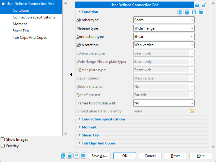
 Condition
Member type: Beam or Column or Vertical brace or Horizontal brace or Joist. Select the member type that this connection will be designed for.
Material type: Options vary by Member type. This is the type of material that matches the section size(s) of the Member type you apply this connection to. See the links below for more information about material types by member type.
Beam Column Horizontal Brace Vertical Brace Joist
Connection type: This is the type of connection to be applied to the selected Member type. Different types of connections are available for the different types of members. See the links below for more information about connection types by member type.
Beam Column Horizontal Brace Vertical Brace Joist
Tip: Different connection specification options appear on this window depending on the selection you make here.
Web rotation: Automatic or Web normal or Web vertical or Hip & valley. This applies when the Member type is Beam. For more information, see Web rotation.
VBrace plate type: Beam only or Column only or Beam and column or Brace intersection plate or Shared 'K' connection or Column and base/cap plate or Three point connection. This applies when the Member type is Vertical brace and the Material type is Channel, Angle, Pipe, W Tee, HSS/TS, Round bar, or S Tee. Select the option that describes the framing condition for this brace.
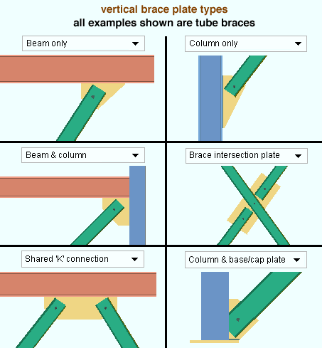
Select Beam only if the vertical brace connects to a gusset on a beam.
Select Column only if the vertical brace connects to a gusset on a column.
Select Beam and column if the vertical brace connects to a gusset shared by a beam and column,
Select Brace intersection plate if the connection is a plate where two vertical braces intersect with each other.
Select Shared K connection if the vertical brace connects to a gusset on a column or beam that also supports another brace.
Select Column and base/cap plate if the vertical brace connects to the end of a column and base/cap plate.
Select Three point connection if you are defining this connection for three vertical braces with a shared gusset.
Wide flange VBrace plate type: Beam only or Column only or Beam and column or Brace intersection plate or Shared 'K' connection or Column and base/cap plate or Three point connection. This applies when the Member type is Vertical brace and the Material type is Wide flange, Welded plate wide flange, or S shape.
Select Beam only if the wide flange vertical brace connects to a gusset on a beam.
Select Column only if the wide flange vertical brace connects to a gusset on a column.
Select Beam and column if the wide flange vertical brace connects to a gusset shared by a beam and column.
Select Brace intersection plate if the wide flange vertical brace connection is a plate where two vertical braces intersect with each other.
Select Shared K connection if the wide flange vertical brace connects to a gusset on a column or beam that also supports the end of another brace.
Select Column and base/cap plate if the wide flange vertical brace connects to the end of a column and base/cap plate.
Select Three point connection if you are defining this connection for three vertical braces with a shared gusset.
HBrace plate type: Beam web or Brace intersection plate or Two point shared gusset or Beam to beam corner or Beam flange or Perpendicular to beam or Beam to beam - column or Three point shared gusset. This applies when the Member type is Horizontal brace. Choose the option that describes the framing situation for this brace.
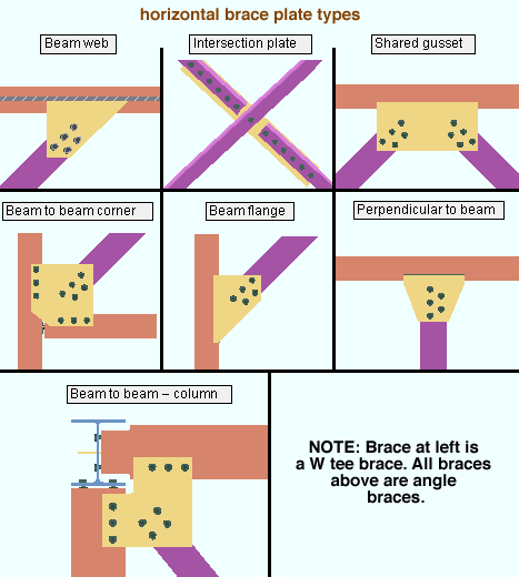
Select Beam web if the horizontal brace connects to a beam web.
Select Brace intersection plate if the connection is a plate where two horizontal braces intersect with each other.
Select Two point shared gusset if the horizontal brace connects to a gusset shared by one other horizontal brace.
Select Beam to beam corner if the horizontal brace connects to a gusset on a beam-to-beam corner.
Select Beam flange if the horizontal brace frames to a beam flange.
Select Perpendicular to beam if the horizontal brace frames perpendicular to a beam.
Select Beam to beam - column if the horizontal brace frames to two beams which frame to a column.
Select Three point shared gusset if the horizontal brace connects to a gusset shared by two other horizontal braces.
Brace rotation: Web vertical or Web horizontal or Stem vertical or Stem horizontal. This applies when the Member type is Vertical brace and the Material type is Wide Flange, Welded plate wide flange, S shape, W Tee, or S Tee. For more information, see Web orientation and Stem orientation.
Double material: No or Yes. This applies when the Member type is a Vertical brace or Horizontal brace and the Material type is Angle.
If No is selected, the brace is a single angle. Also see Side of gusset.
If Yes is selected, the brace is two angles. Also see Configuration (vertical brace) and Side of gusset (horizontal brace).
Side of gusset: Near side or Far Side or Both sides (horizontal brace only). This applies when the Member type is a Vertical brace or Horizontal brace and the Material type is Angle. For more information, see Side of gusset (vertical brace), and Side of gusset (horizontal brace).
Configuration: Back to back or Star or Far side or Near side. This applies when the Member type is a Vertical brace, the Material type is Angle, and Double material is set to Yes. For more information, see Configuration.
Frames to concrete wall: No or Yes. This applies when the Member type is a Beam and the Connection type is Shear or Clip angle or Seated or Bearing or Plain end. It also applies when the Member type is Joist and the Connection type is Bearing or Seated.
If Yes is selected, the connection is designed for the framing condition of a beam (or joist) to a concrete wall. Yes must be selected when the Connection type is Bearing. When the Member type is Beam, Embed schedule entry is enabled.
If No is selected, the connection is designed for a non-concrete framing condition.
Embed schedule entry: A standard piecemark name from the Piecemark column in the Embed Schedule. This applies when Frames to concrete wall is set to Yes.
For more information about beam-to-concrete connections, please see Embed schedule entry (Beam Edit window).
For more information about joist-to-concrete connections, please see Top chord embed and Bottom chord embed (Joist Edit window).
Connection specifications
Connection specifications is populated with additional options based on the Connection type you select. They are the same connection specifications found on member edit windows. See the links below for more information about connection specifications by member type.
Beam Column Horizontal Brace Vertical Brace Joist
Moment
Moment options are applicable when the Member type is Beam and the Connection type is Clip angle, End plate, Shear, Splice plate, or Fully welded moment. These are the same moment options found on the Beam Edit window.
Connection design locks
Connection design locks are stored under leaves which have various names. They are the same connection design locks found on member edit and connection component edit windows. See the links below for more information about connection design locks by member type.
Beam Column Horizontal Brace Vertical Brace Joist
 Lock / Unlock: Sets all connection design locks to be locked or unlocked.
Show images:  or
or  . When checked, drawings that depict the dimensions that are controlled by connection design locks are shown on the window.
Overlay: or . When checked, one leaf at a time is displayed. When you select a leaf, all others collapse.
![]() Copy, Paste, Save, Load buttons:
Copy, Paste, Save, Load buttons:
- The position of these "form" buttons on the window tells you what settings they apply to. Click here for more information.
- You can
 Copy the settings on this window, then
  Paste those settings to a different edit window of the same type.
- You can
 Save the settings on this window to a file stored in a global folder that is used by your current version of SDS2. Give the file a name that will help other users identify its purpose. You can
  Load a saved file to replace the settings on this window (except Piecemark) with the settings that are stored in the file you select.
- When editing multiple windows at the same time, Paste and Load replace mixed entries to a single field with a single entry. Copy and Save ignore fields with mixed entries, treating them as if they have no entry or do not exist.
![]()
![]()
![]()
![]()
Save As opens the Select One User Defined Connection dialog, giving you the ability to overwrite a selected file with your current settings or to write your current settings to a new file.
OK saves the changes you have made to the connection you have created or redefined. The changes are saved to the file name that is printed at the top of the User Defined Connection Edit window, which then closes.
Cancel closes the User Defined Connections window without saving any changes that you may have made to it.
Reset undoes any changes that were made since you first opened the User Defined Connection Edit window.
Home > Project Settings > Job > Connections > User Defined Connections
1. Click User Defined Connections found on the Home > Project Settings > Job > Connections screen.
2. The Select one User Defined Connection window opens. Click the New... button to create a new user defined connection.
Alternative 1: To edit an existing user defined connection, select it and click OK, or double-click it.
Alternative 2: Click the Cancel button to close the Select one User Defined Connection window.
3. The User defined connection name input window opens. Type in a name for the connection (61 characters max.) and click OK.
Alternative: Click the Cancel button to close the User defined connection name input window and return to the Select one User Defined Connection window.
4. The User Defined Connection Edit window opens. Set the Condition options starting at the top of the list and working down.
Condition options above can affect the options below, and can also enable a disabled (grayed out) Condition option. The Condition options also determine which Connection specifications and connection design locks are available in this window. When the Member type is set to Beam, Moment options are also available.
Alternative: Click the Cancel button to close User Defined Connection Edit window and return to the Select one User Defined Connection window. Any changes you made to the settings are not saved.
5. Set the Connection specifications, connection design locks, and moment options. Click OK to save the user defined connection.
Alternative 1: Click the Save As... button. The Select one User Defined Connection window opens. Click the New button to create a new user defined connection with a new name, or select an existing connection to save over it.
Alternative 2: Click the Cancel button to close User Defined Connection Edit window and return to the Select one User Defined Connection window. Any changes you made to the settings are not saved.
Member Edit or Connection Component Edit > Save As User Defined Connection
1. After you set the Connection specifications, connection design locks, and Moment options on the member edit or connection component edit window, click the Save As User Defined Connection button found on the end settings/connection decoration bar.
2. The Select one User Defined Connection window opens. Click the New... button to create a new user defined connection using the current Connection specifications, connection design locks, and Moment options of the edit window.
Alternative 1: To save over an existing user defined connection and replace its settings with the current settings of the edit window, select it and click OK, or double-click it. Click Yes or No on the prompt window asking if you want to overwrite the connection. The user defined connection is immediately saved. There are no further steps to take.
Alternative 2: Click the Cancel button to close the Select one User Defined Connection window.
3. The User defined connection name input window opens. Type in a name for the connection (61 characters max.) and click OK to save the new user defined connection.
Alternative: Click the Cancel button to close the User defined connection name input window and return to the Select one User Defined Connection window.
- A user defined connection lets a user employ connection design locks to specify, for example, the plate thickness or number of rows of bolts to be used by connection design when it creates the connection. The connection will undergo capacity checks, bolt validations, and other failure checks.
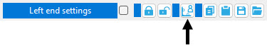
- Instead of setting up a user defined connection from Job Settings, you can set up the connection on a member edit window and save it from there. A Save As User Defined Connection button (
 ) can be found embedded in the Left end settings and Right end settings banners of the Beam, Column, Horizontal Brace, Vertical Brace and Joist windows. A similar button is also found on the Connection Component Edit window.
- You can set up the user defined connection to be applied as an auto standard connection. This causes it to be automatically applied to particular framing conditions where Auto standard is the Input connection type on a member edit window.
- When applying a user defined connection to a member, confirm that the member's Section size matches with the Material type selected for the user defined connection.

