Auto Standard Connections
- General Overview
- Tips and Tricks
- Related Tools
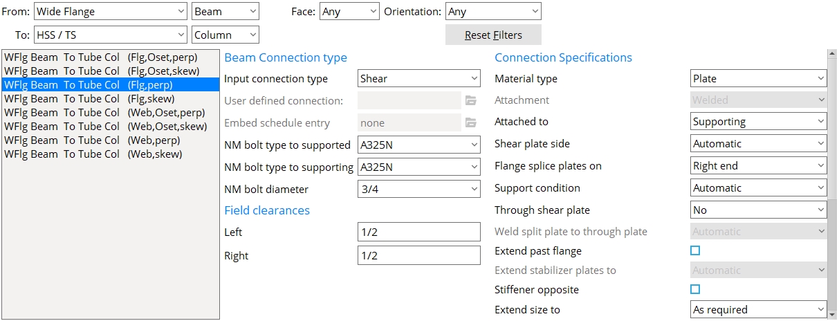
Filters
From: Filters the list of framing conditions by either the material type (first drop-down) and/or the member type (second drop-down) for the supported member.
To: Filters the list of framing conditions by either the material type (first drop-down) and/or the member type (second drop-down) for the supporting member.
Face: Filters the list of framing conditions by the face of the supporting member.
Orientation: Filters the list of framing conditions by the orientation of the supported member to the supporting member.
Reset Filters: Clears any of the set filters.
Framing conditions: A list of the framing conditions you can select to set up the auto standard connection.
Connection Type
Input connection type: See table below.
| Connection
Specifications |
General Framing Condition |
| User defined | beam to beam, beam to column, column to beam, or column to column |
| Plain end | beam to beam, beam to column, column to beam, or column to column |
| Clip angle | beam to beam or beam to column |
|
beam to embed plate
|
|
| Bent plate | beam to beam or beam to column |
| End Plate | beam to beam or beam to column |
| Shear | beam to beam or beam to column |
|
beam to embed plate
|
|
| Seated beam | beam to column |
| beam to embed | |
| Bearing
(beam) |
beam to concrete |
| Splice plate (beam) | beam to beam |
|
Splice plate
(column) |
column to column |
| Auto base/cap plate | column to beam |
| User base/cap plate | column to beam |
| Clip angle hanger connection | column to beam |
| Shear hanger connection | |
| Bearing
(joist) |
joist to beam |
|
joist to concrete wall
|
|
| Joist seats | joist to column |
|
joist to embed plate
|
|
| Flush framed shear
& Flush framed clip |
joist to beam,
joist to column |
| Joist bottom chord stabilizer | joist bottom chord to column |
| joist bottom chord to embed plate |
User defined connection: This applies when ' User defined ' is selected as the Input connection type . You can type in the name of the user defined connection that you want, or you can press the "file cabinet" browse button ( ![]() ) and double-click a user defined connection that is on the list. Validation does not let you apply a file that is inappropriate to the framing condition.
) and double-click a user defined connection that is on the list. Validation does not let you apply a file that is inappropriate to the framing condition.
Embed schedule entry: A standard piecemark name from the " Piecemark " column in the Embed Schedule . This option can apply when the " General framing condition " is ' Beam to concrete ' and, in the model, the beam frames to a concrete wall . The " Input connection type " must be 'Shear' or 'Clip angle' or 'Bent plate' or 'Seated' or 'Plain end'.
|
For a beam to concrete, entering an " Input connection type " of 'Shear' or 'Clip angle' or 'Seated' or 'Bent plate' creates a connection that field welds to the " Embed schedule entry ." |
|
When ' Bearing ' is the " Input connection type " for a beam to concrete, a bearing angle (shown) or bearing plate or bearing channel can be created along with a pocket into the concrete wall. The angle, plate or channel embed is selected as the " Embed schedule entry ." |
NM bolt type: A325N or A325SC or A325X or etc. NM stands for "non-moment." Select from the list box ( ![]() ) the type of non-moment bolt to be used for the connection. Bolt types listed on the menu come from the Bolt Settings .
) the type of non-moment bolt to be used for the connection. Bolt types listed on the menu come from the Bolt Settings .
NM bolt diameter: The diameter of the shank of the bolt specified above. You can either type in the diameter of bolt, or select a bolt from the combo box ( ![]() ). Bolt diameters listed on the menu come from Home > Project Settings > Job > Bolt Settings > " Available bolt diameters ."
). Bolt diameters listed on the menu come from Home > Project Settings > Job > Bolt Settings > " Available bolt diameters ."
Field Clearances
Left/Right: The field clearance for the connection on the left end of the beam. How field clearance is measured depends on the connection type.
fc = field clearance. For a clip angle (except as noted below) or bent plate or end plate connection, the field clearance is the distance from the face of the connection to the face of the supporting member.
fc = field clearance. For clip angles that shop weld to the supporting member (knife connections), the field clearance is measured from the face of the supporting member to the web of the beam that the clip angles field bolt to.
fc = field clearance. For seated beam connections , the field clearance is the distance from the face of the beam to the flange of the column being framed to.
fc = field clearance. For shear plates , fc is the distance between the end of the beam to the face of the supporting member or, if the plate extends past the supporting beam's flange, the distance between the beams.
Shear connection field clearances: If " Automatic minus dimension " is used, connection design calculates the distance from the face of the support to the hole column in the shear plate using the field clearance entered here plus the end edge distance of the beam. This is then rounded up to the nearest 1/4 inch (or even millimeters for metric). As a result, the actual calculated field clearance may be greater than specified, but not less. For shear plates on a sloping beam with a square cut end, the calculated field clearance will never be more than 1/8 inch larger than specified here.


|
|
OK (or the Enter key) closes this screen and applies the settings.
Cancel (or the Esc key) closes this screen without saving any changes.
Reset undoes all changes made to this screen since you first opened it. The screen remains open.
- If you set a member's " Input connect type " to Auto standard, the member will not display any connection specifications.
- Red or yellow exclamation point icons
 or
or 
- Connections you can't define as auto standard:
- System connection types (most can be auto standard)
- Ways to get connections (topic)
- Default non-moment bolt diameter and type ( Home > Project Settings > Job > Bolt Settings )
- Washer Settings ( Home > Project Settings > Job )
- Weld Design Settings ( Home > Project Settings > Job for welds on connections)
- Base/Cap Plate Schedule ( Home > Project Settings > Job for auto standard user base/cap plates)
- Status Display ( Connection type > Auto standard )

