Base/Cap Plate Schedule
- General Overview
- Tips and Tricks
- Related Tools
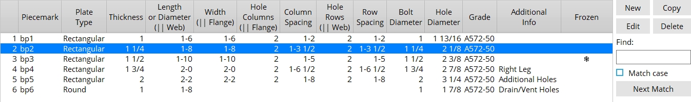
Base/Cap Plate Schedule
New: Opens the Base/Cap Plate Options screen so you can add a new plate to the schedule.
Copy: Opens the Base/Cap Plate Options screen and copies the settings of the selected plate so you can add a new plate to the schedule. This button is deactivated when a plate is not selected.
Edit: Opens the Base/Cap Plate Options screen so you can edit the selected plate. This button is deactivated when a plate is not selected.
Tip: You can also double-click a schedule entry to edit it.
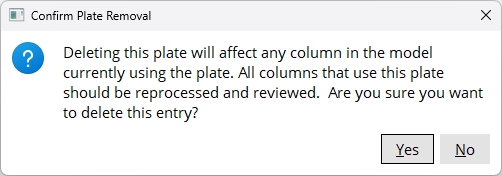
Delete: Deletes the selected plate. The Confirm Plate Removal window opens first, asking you to confirm the removal of the plate from your Job. This button is deactivated when a plate is not selected or if the selected plate is Frozen.
Find: The Find widget searches the schedule for piecemarks and selects the closest match. Match case performs a case-sensitive search. Next Match cycles to the next piecemark that closely matches the search criteria.
Additional Info: This information lets you know when a plate utilizes Left Side, Right Side, Top Side, Bottom Side, Additional Holes, and Drain/Vent Holes.
Frozen: A snowflake icon  )
)
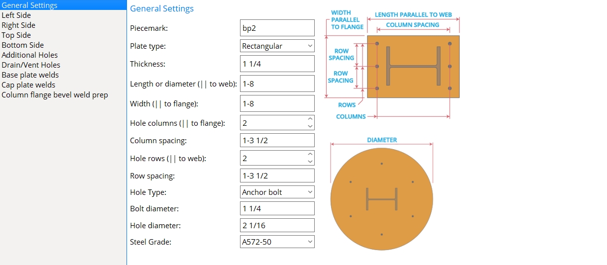
Base/Cap Plate Options
The Base/Cap Plate Options screen is opened by clicking New, Copy, Edit, or by double-clicking a schedule entry on the Base/Cap Plate Schedule screen.
General Settings
Piecemark: The standard submaterial mark (standard mark of up to 61 characters) that you want to assign to all copies of this particular plate when added to column members.
Note: The piecemark entered here must be unique. If the piecemark you enter is already assigned to another material, a red exclamation point appears
( and prevents you from clicking OK until you change your entry to a unique piecemark.)
Plate type: Rectangular or Round.
Rectangular

|
Round

|
Rectangular lets you define a rectangular plate. You can use Left Side, Right Side, Top Side, and Bottom Side options to define an L-shaped, X-shaped, or T-shaped plate when Rectangular is selected.
Round lets you define a round plate. Round Plate Holes appears on the options menu when Round is selected.
Thickness: The Material thickness of the plate.
To enter gage plate: Type in the gage number followed by ga. For example, 4ga is rewritten as 4GA when you Tab or click out of the field.
Allowable gages are any whole number from 3 to 10. Gages greater than 10 designate a thickness less than 0.125 inch, which is not allowed.
Right-click tells you the stored thickness (based on industry standards), from which the weight of the gage plate is calculated.
You can also enter an exact decimal thickness to get the gage. For example, .1345 becomes 10GA when you Tab or click out of the field.
The Description for a gage plate follows the format: plate prefix + numberGA + x + width (e.g., PL16GAx15 1/2).
Length or Diameter (parallel to web *): The Order length of a rectangular base/cap plate that is parallel to the column web, or the Plate diameter of a round base/cap plate. Lengths as small as 1/4 inch (6 mm) and as great as 20-0 feet (6069 mm) are permitted.
* For a column under or over a beam, or when a joist frames to a column with a user cap plate, the length of the base/cap plate is automatically rotated to be parallel to the work line of the beam or joist no matter how the column is rotated.
Width (parallel to flange *): The Material width of the base/cap plate that is parallel to the column flanges as shown in cross section. Widths as small as 1/4 inch (6 mm) and as great as 20-0 feet (6069 mm) are permitted.
* For a column under or over a beam, or when a joist frames to a column with a user cap plate, the width of the base/cap plate is automatically rotated perpendicular to the work line of the beam or joist no matter how the column is rotated.
Hole Columns: The quantity of hole columns. Hole columns run parallel with the column flanges (or perpendicular to the beam/joist workline when the column frames under/over a beam/joist).
|
If Plate rotation is 0 for a user base/cap plate on a column with an indeterminate end, hole columns run parallel with the column flanges. |
|
If Plate rotation is 0 for a user base/cap plate on a column to a beam or joist, hole columns run perpendicular to the work line of the beam or joist. |
Note: When there are an odd number of columns of holes (1, 3, 5, 7, etc.), the middle column is centered with respect to the length of the base/cap plate.
Column Spacing: The center-to-center distance between columns of holes. This distance is measured parallel with the column web (or parallel with the beam/joist workline).
|
x = column spacing. If Plate rotation is 0 for a user base/cap plate on a column with an indeterminate end, column spacing is horizontal when the Column rotation is 0. |
|
x = column spacing. If Plate rotation is 0 for a user base/cap plate on a column to a beam or joist, hole spacing runs parallel with the work line of the beam or joist. The Column rotation does not matter. |
Hole Rows: The quantity of hole rows. Hole rows run parallel with the column web (or parallel with the beam/joist workline when the column frames under/over a beam/joist).
|
If Plate rotation is 0 for a user base/cap plate on a column with an indeterminate end, hole rows runs parallel with the column web. |
|
If Plate rotation is 0 for a user base/cap plate on a column to a beam or joist, hole rows run parallel with the work line of the beam or joist. |
Note: When there are an odd number of rows of holes (1, 3, 5, 7, etc.), the middle row is centered with respect to the width of the base/cap plate.
Row Spacing: The center-to-center distance between rows of holes. This distance is measured parallel with the column flange (or perpendicular to the beam/joist work line when the column frames under/over a beam/joist).
|
Y = row spacing. If Plate rotation is 0 for a user base/cap plate on a column to nothing, row spacing is vertical when the Column rotation is 0. |
|
Y = row spacing. If Plate rotation is 0 for a user base/cap plate on a column to a beam or joist, row spacing is vertical when the work line of the beam or joist is horizontal. The Column rotation does not matter. |
Hole Type: Anchor bolt hole or Standard round or Oversized. The selection made here is used to calculate the default Hole Diameter.
An Anchor bolt hole is a hole for anchor bolts in a column base plate. Holes must be this type in order for them to be automatically dimensioned when the Dimension anchor bolt layout option is selected during erection view detailing. This hole type also allows you to use the Anchor Rod Tool to quickly add 3D Anchor Rod members.
A Standard round is a hole for standard bolt types. 3D bolts can potentially be generated when the column member frames to a supporting beam or joist.
An Oversized is a hole for standard bolt types. 3D bolts can potentially be generated when the column member frames to a supporting beam or joist.
Bolt Diameter: The diameter (inches or mm) of the shank of the bolt to be inserted into the plate. The entry or selection made here is used to calculate the default Hole Diameter.
| diameter |
|
To make an entry: You can either type in the diameter of bolt or select a bolt diameter from the combo box
( . Diameters listed in the combo box come from Home > Project Settings > Job > Bolt, Washers, and Holes > Bolt Settings > Available bolt diameters.)
Hole Diameter: 0 (zero) or a distance to designate the hole diameter. The default value is calculated from the Hole type and Bolt diameter according to your selected connection design method.
0 (zero) designates a CNC mark. Entering 0 to this field does not stop holes from being created. To prevent holes from being created, enter 0 to Column Spacing and Row Spacing.
Steel Grade: A36 or A572-50 or etc.
When creating a new plate, the default steel grade comes from Home > Project Settings > Job > Design > Design Settings > Connection material specifications > Base/Cap plate schedule.
All steel grades populating this list box (
Round Plate Holes
The Round Plate Holes options screen populates the options menu when the Plate type is set to Round.
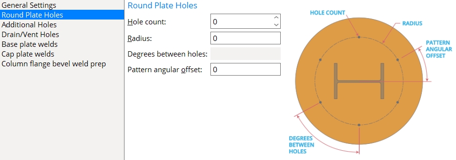
Hole count: This is the total number of holes in a round plate.
Radius: The distance from the center of the round plate to the center of all holes in the circular hole pattern.
Degrees between holes: (READ-ONLY) The number of degrees between each hole in the circular hole pattern. The number you see here is the result of 360° divided by the Hole count.
Pattern angular offset: The number of degrees the circular hole group is offset from the 0° base line. A positive number offsets the pattern counterclockwise. A negative number offsets the pattern clockwise.
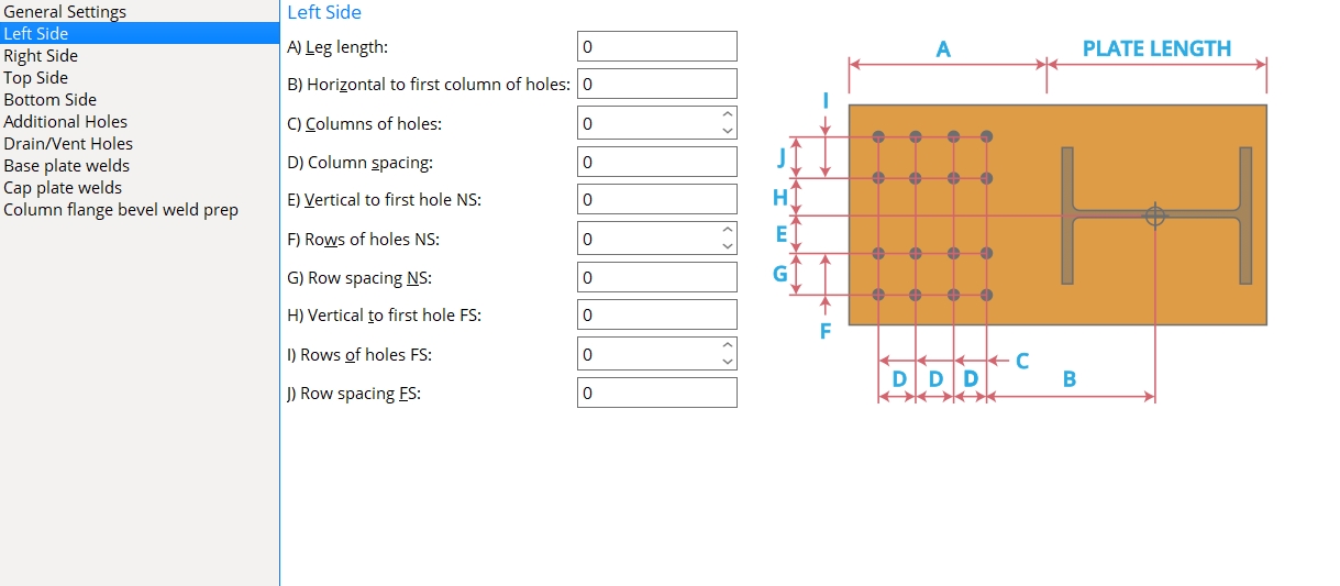
Left Side
Leg length: The length of the left leg measured from the left edge of the rectangular base plate to the outside edge of the left leg.
|
l = leg length |
Horizontal to first column of holes: The distance measured parallel with the Leg length from the center of the rectangular plate to the first column of holes in the left leg.
|
hc = horizontal to first column of holes |
Columns of holes: The number of columns of holes located on the left leg.
|
c = columns of holes |
Column spacing: The center-to-center distance measured between columns of holes.
|
csp = column spacing |
Vertical to first hole NS: The distance measured perpendicular to the Leg length from the center of the rectangular plate to the first row of holes in the near side of the left leg.
|
vns = vertical to first hole NS |
Rows of holes NS: The number of rows of holes in the near side of the left leg.
|
rns = rows of holes NS |
Row spacing NS: The center-to-center distance measured between rows of holes in the near side of the left leg.
|
sns = row spacing NS |
Vertical to first hole FS: The distance measured perpendicular to the Leg length from the center of the rectangular plate to the first row of holes in the far side of the left leg.
|
vfs = vertical to first hole FS |
Rows of holes FS: The number of rows of holes in the far side of the left leg.
|
rfs = rows of holes FS |
Row spacing FS: The center-to-center distance measured between rows of holes in the far side of the left leg.
|
sfs = row spacing FS |
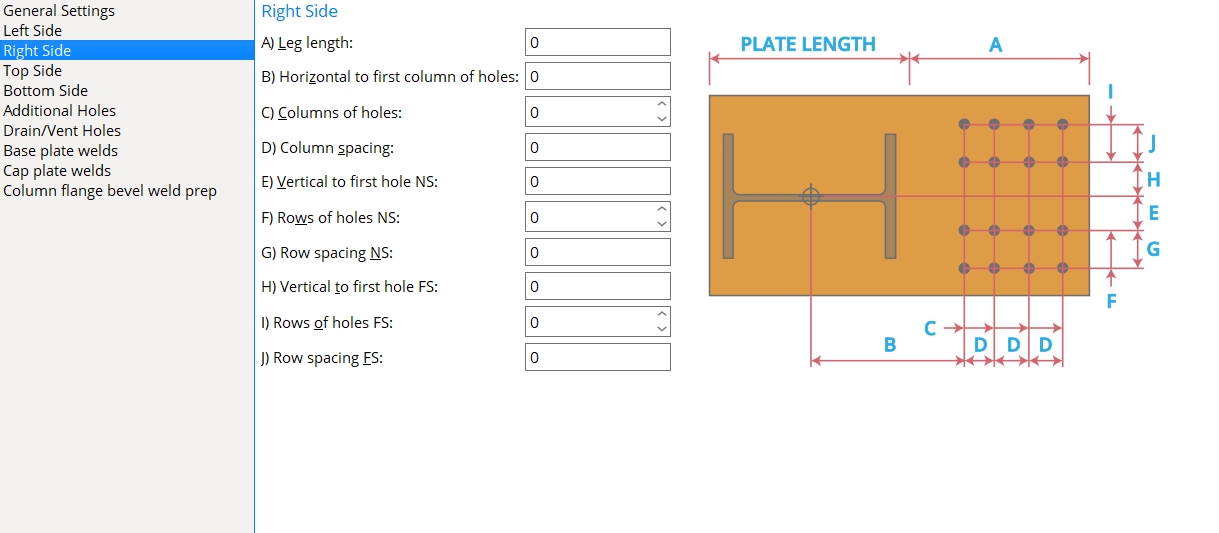
Right Side
| l = leg length hc = horizontal to first column of holes c = columns of holes csp = column spacing vns = vertical to first hole NS rns = rows of holes NS sns = row spacing NS vfs = vertical to first hole FS rfs = rows of holes FS sfs = row spacing FS |
|
Leg length: The length of the right leg measured from the right edge of the rectangular base plate to the outside edge of the right leg.
Horizontal to first column of holes: The distance measured parallel with the Leg length from the center of the rectangular plate to the first column of holes in the right leg.
Columns of holes: The number of columns of holes located on the right leg.
Column spacing: The center-to-center distance measured between columns of holes.
Vertical to first hole NS: The distance measured perpendicular to the Leg length from the center of the rectangular plate to the first row of holes in the near side of the right leg.
Rows of holes NS: The number of rows of holes in the near side of the right leg.
Row spacing NS: The center-to-center distance measured between rows of holes in the far side of the right leg.
Vertical to first hole FS: The distance measured perpendicular to the Leg length from the center of the rectangular plate to the first row of holes in the far side of the right leg.
Rows of holes FS: The number of rows of holes in the far side of the right leg.
Row spacing FS: The center-to-center distance measured between rows of holes in the far side of the right leg.
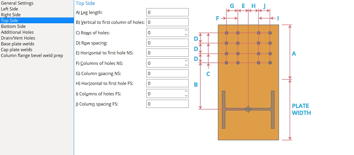
Top Side
| l = leg length
vc = vertical to first column of holes r = rows of holes rs = row spacing ns = horizontal to first hole NS cns = columns of holes NS sn = column spacing NS fs = horizontal to first hole FS cfs = columns of holes FS sf = column spacing FS |
|
Leg length: The length of the top leg measured from the top edge of the rectangular base plate to the outside edge of the top leg.
Vertical to first column of holes: The distance measured parallel with the Leg length from the center of the rectangular plate to the first column of holes in the top leg.
Rows of holes: The number of columns of holes located on the top leg.
Row spacing: The center-to-center distance measured between columns of holes.
Horizontal to first hole NS: The distance measured perpendicular to the Leg length from the center of the rectangular plate to the first row of holes in the near side of the top leg.
Columns of holes NS: The number of rows of holes in the near side of the top leg.
Column spacing NS: The center-to-center distance measured between rows of holes in the far side of the top leg.
Horizontal to first hole FS: The distance measured perpendicular to the Leg length from the center of the rectangular plate to the first row of holes in the far side of the top leg.
Columns of holes FS: The number of rows of holes in the far side of the top leg.
Column spacing FS: The center-to-center distance measured between rows of holes in the far side of the top leg.
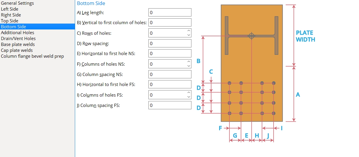
Bottom Side
| l = leg length
vc = vertical to first column of holes r = rows of holes rs = row spacing ns = horizontal to first hole NS cns = columns of holes NS sn = column spacing NS fs = horizontal to first hole FS cfs = columns of holes FS sf = column spacing FS |
|
Leg length: The length of the bottom leg measured from the bottom edge of the rectangular base plate to the outside edge of the bottom leg.
Vertical to first column of holes: The distance measured parallel with the Leg length from the center of the rectangular plate to the first column of holes in the bottom leg.
Rows of holes: The number of columns of holes located on the bottom leg.
Row spacing: The center-to-center distance measured between columns of holes.
Horizontal to first hole NS: The distance measured perpendicular to the Leg length from the center of the rectangular plate to the first row of holes in the near side of the bottom leg.
Columns of holes NS: The number of rows of holes in the near side of the bottom leg.
Column spacing NS: The center-to-center distance measured between rows of holes in the far side of the bottom leg.
Horizontal to first hole FS: The distance measured perpendicular to the Leg length from the center of the rectangular plate to the first row of holes in the far side of the bottom leg.
Columns of holes FS: The number of rows of holes in the far side of the bottom leg.
Column spacing FS: The center-to-center distance measured between rows of holes in the far side of the bottom leg.
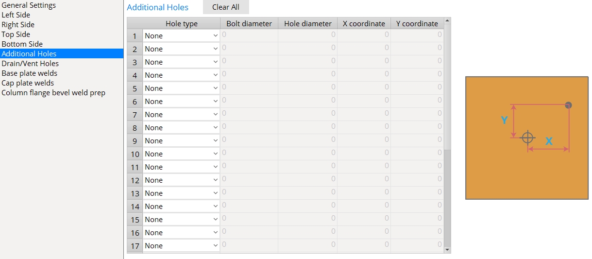
Additional Holes
Hole type: None or Grout or Vent/Drain or Standard round or Oversized round or Cope hole or Anchor bolt hole or Plug weld hole.
When None is selected, an additional hole is not added to the plate.
When one of the other options is selected, an additional hole is added to the plate with its Hole type set to that particular option.
Bolt diameter: the diameter of the bolt when the Hole type is set to Standard round, Oversized round, or Anchor bolt hole. Bolts can be generated automatically by Process and Create Solids when the base/cap plate frames to a beam's top or bottom flange.
Hole Diameter: the diameter of the additional hole based on the selected Hole type.
X coordinate: The distance the hole is located from the center of the plate along the X axis (right-to-left). A positive number locates the hole right-of-center. A negative number locates the hole left-of-center. Zero (0) locates the hole at the center of the plate.
Y coordinate: The distance the hole is located from the center of the plate along the Y axis (top-to-bottom). A positive number locates the hole above the center. A negative number locates the hole below the center. Zero (0) locates the hole at the center of the plate.
Clear All: Clicking this button resets all Hole types to None.
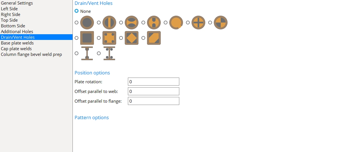
Drain/Vent Holes
Hole Patterns: None or Pipe or Tube or Wide Flange.


Position options
Plate rotation: The number of degrees the hole pattern is rotated on the plate.
Offset parallel to web: To keep the pattern centered on the column member, the value entered here should match the value entered for Offset parallel to web on the Column Edit window.
Offset parallel to flange: To keep the pattern centered on the column member, the value entered here should match the value entered for Offset parallel to flange on the Column Edit window.
Pattern options


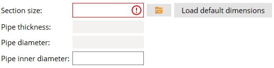
Section Size: The section size you enter here must be found in your job's local shape file. It should also match the value entered for Section size on the Column Edit window you intend to use this base/cap plate on.
Pipe thickness: (READ-ONLY) The wall thickness of the selected pipe section size.
Pipe diameter: (READ-ONLY) The depth (outside diameter) of the selected pipe section size.
Pipe inner diameter: The inner diameter is automatically calculated based on the depth (outside diameter) and wall thickness. This value can be adjusted to change the size of the pattern.
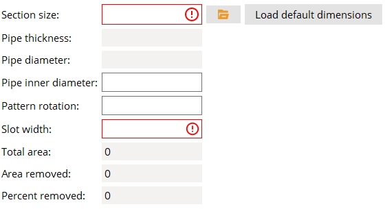
Pattern rotation: The degrees of rotation the pattern is rotated around its center.
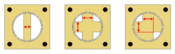
Slot width: The width of the remaining material between the openings in the plate.
Total area: (READ-ONLY) The area of plate material located within the Pipe inner diameter.
Area removed: (READ-ONLY) The area of material that is removed from the plate located within the Pipe inner diameter.
Percent removed: (READ-ONLY) The percentage of the plate material that is removed to make the vent/drain opening. The recommended AGA standard is to remove at least 30 percent of the inner diameter area.

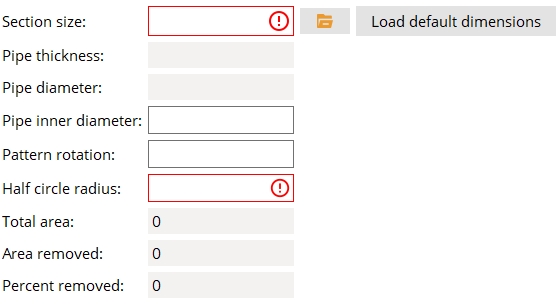
Section Size: The section size you enter here must be found in your job's local shape file. It should also match the value entered for Section size on the Column Edit window you intend to use this base/cap plate on.
Pipe thickness: (READ-ONLY) The wall thickness of the selected pipe section size.
Pipe diameter: (READ-ONLY) The depth (outside diameter) of the selected pipe section size.
Pipe inner diameter: The inner diameter is automatically calculated based on the depth (outside diameter) and wall thickness. This value can be adjusted to change the size of the pattern.
Pattern rotation: The degrees of rotation the pattern is rotated around its center.
Half circle radius: The radius of the circular opening measured from the midpoint of the outside edge of the circular opening to the inside edge of the circular opening.
Total area: (READ-ONLY) The area of plate material located within the Pipe inner diameter.
Area removed: (READ-ONLY) The area of material that is removed from the plate located within the Pipe inner diameter.
Percent removed: (READ-ONLY) The percentage of the plate material that is removed to make the vent/drain opening. The recommended AGA standard is to remove at least 30 percent of the inner diameter area.

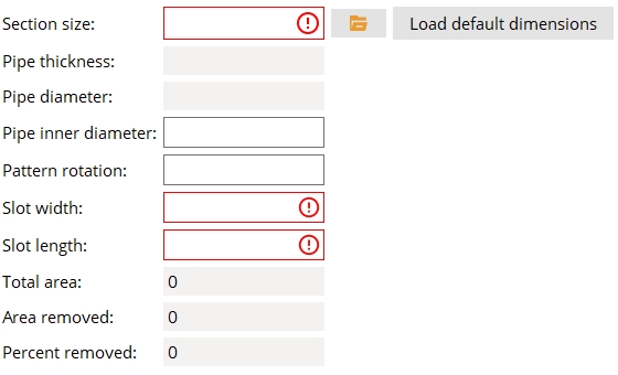
Section Size: The section size you enter here must be found in your job's local shape file. It should also match the value entered for Section size on the Column Edit window you intend to use this base/cap plate on.
Pipe thickness: (READ-ONLY) The wall thickness of the selected pipe section size.
Pipe diameter: (READ-ONLY) The depth (outside diameter) of the selected pipe section size.
Pipe inner diameter: The inner diameter is automatically calculated based on the depth (outside diameter) and wall thickness. This value can be adjusted to change the size of the pattern.
Pattern rotation: The degrees of rotation the pattern is rotated around its center.
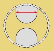
Slot width: The distance measured between the edges of the opening that intersect the Pipe inner diameter.
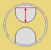
Slot length: The distance measured from where the edges of the opening intersect the Pipe inner diameter to the midpoint of the circular edge.
Total area: (READ-ONLY) The area of plate material located within the Pipe inner diameter.
Area removed: (READ-ONLY) The area of material that is removed from the plate located within the Pipe inner diameter.
Percent removed: (READ-ONLY) The percentage of the plate material that is removed to make the vent/drain opening. The recommended AGA standard is to remove at least 30 percent of the inner diameter area.

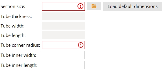
Section size: The section size you enter here must be found in your job's local shape file. It should also match the value entered for Section size on the Column Edit window you intend to use this base/cap plate on.
Tube thickness: (READ-ONLY) The wall thickness of the selected tube section size.
Tube width: (READ-ONLY) The outside width of the HSS material.
Tube length: (READ-ONLY) The outside length of the HSS material.
Tube corner radius: The dimension applied to the corner radius of the opening. The default dimension matches the inner corner radius of the HSS material.
Tube inner width: The width of the opening. The default dimension matches the inner width of the HSS material.
Tube inner length: The length of the opening. The default dimension matches the inner length of the HSS material.

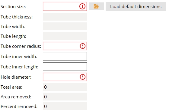
Section size: The section size you enter here must be found in your job's local shape file. It should also match the value entered for Section size on the Column Edit window you intend to use this base/cap plate on.
Tube thickness: (READ-ONLY) The wall thickness of the selected tube section size.
Tube width: (READ-ONLY) The outside width of the HSS material.
Tube length: (READ-ONLY) The outside length of the HSS material.
Tube corner radius: The default dimension matches the inner corner radius of the HSS material.
Tube inner width: The width at which the outermost edge of the holes is located. The default dimension matches the inner width of the HSS material.
Tube inner length: The length at which the outermost edge of the holes is located. The default dimension matches the inner length of the HSS material.
Hole diameter: The diameter of the four holes.
Total area: (READ-ONLY) The area of plate material located within the Tube inner width and Tube inner length.
Area removed: (READ-ONLY) The area of material that is removed from the plate located within the Tube inner width and Tube inner length.
Percent removed: (READ-ONLY) The percentage of the plate material that is removed to make the vent/drain openings. The recommended AGA standard is to remove at least 30 percent of the inner diameter area.

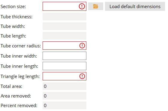
Section size: The section size you enter here must be found in your job's local shape file. It should also match the value entered for Section size on the Column Edit window you intend to use this base/cap plate on.
Tube thickness: (READ-ONLY) The wall thickness of the selected tube section size.
Tube width: (READ-ONLY) The outside width of the HSS material.
Tube length: (READ-ONLY) The outside length of the HSS material.
Tube corner radius: The dimension applied to the corner radius of the openings. The default dimension matches the inner corner radius of the HSS material.
Tube inner width: The width locates the outside edges of the openings. The default dimension matches the inner width of the HSS material.
Tube inner length: The length locates the outside edges of the openings. The default dimension matches the inner width of the HSS material.
Triangle leg length: The length of the triangle legs that form the outside edges of the openings.
Total area: (READ-ONLY) The area of plate material located within the Tube inner width and Tube inner length.
Area removed: (READ-ONLY) The area of material that is removed from the plate located within the Tube inner width and Tube inner length.
Percent removed: (READ-ONLY) The percentage of the plate material that is removed to make the vent/drain openings. The recommended AGA standard is to remove at least 30 percent of the inner diameter area.

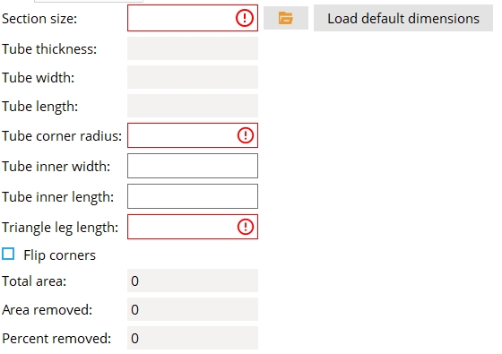
Section size: The section size you enter here must be found in your job's local shape file. It should also match the value entered for Section size on the Column Edit window you intend to use this base/cap plate on.
Tube thickness: (READ-ONLY) The wall thickness of the selected tube section size.
Tube width: (READ-ONLY) The outside width of the HSS material.
Tube length: (READ-ONLY) The outside length of the HSS material.
Tube corner radius: The dimension applied to the corner radius of the opening. The default dimension matches the inner corner radius of the HSS material.
Tube inner width: The width locates the outside edges of the openings. The default dimension matches the inner width of the HSS material.
Tube inner length: The length locates the outside edges of the openings. The default dimension matches the inner width of the HSS material.
Triangle leg length: The length of the triangle legs that form the outside edges of the openings.
Flip corners:  or
or  . When this is checked ( ), the openings are placed on the opposite corners of the HSS shape compared to when this is unchecked )
Total area: (READ-ONLY) The area of plate material located within the Tube inner width and Tube inner length.
Area removed: (READ-ONLY) The area of material that is removed from the plate located within the Tube inner width and Tube inner length.
Percent removed: (READ-ONLY) The percentage of the plate material that is removed to make the vent/drain openings. The recommended AGA standard is to remove at least 30 percent of the inner diameter area.

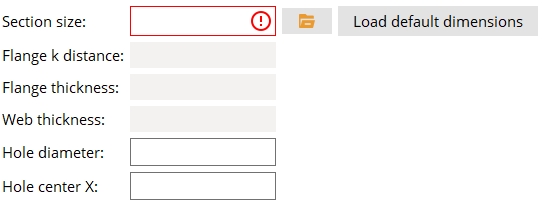
Section size: The section size you enter here must be found in your job's local shape file. It should also match the value entered for Section size on the Column Edit window you intend to use this base/cap plate on.
Flange k distance: (READ-ONLY) The k Distance (detail) for the particular shape you set Section size to.
Flange thickness: (READ-ONLY) The flange thickness of the selected wide flange section size.
Web thickness: (READ-ONLY) The web thickness of the selected wide flange section size.
Hole diameter: The diameter of the two holes.
Hole center X: The location of each hole measured along the X-axis from the center of the pattern to the center of the hole.

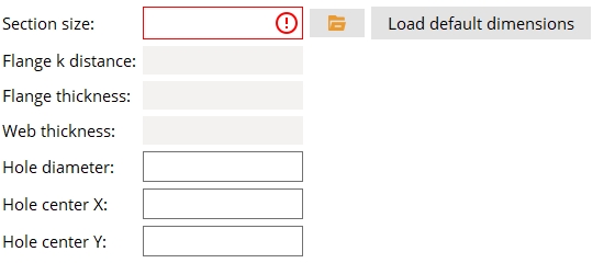
Section size: The section size you enter here must be found in your job's local shape file. It should also match the value entered for Section size on the Column Edit window you intend to use this base/cap plate on.
Flange k distance: (READ-ONLY) The k Distance (detail) for the particular shape you set Section size to.
Flange thickness: (READ-ONLY) The flange thickness of the selected wide flange section size.
Web thickness: (READ-ONLY) The web thickness of the selected wide flange section size.
Hole diameter: The diameter of the four holes.
Hole center X: The location of each hole measured along the X-axis from the center of the pattern to the center of the hole.
Hole center Y: The location of each hole measured along the Y-axis from the center of the pattern to the center of the hole.
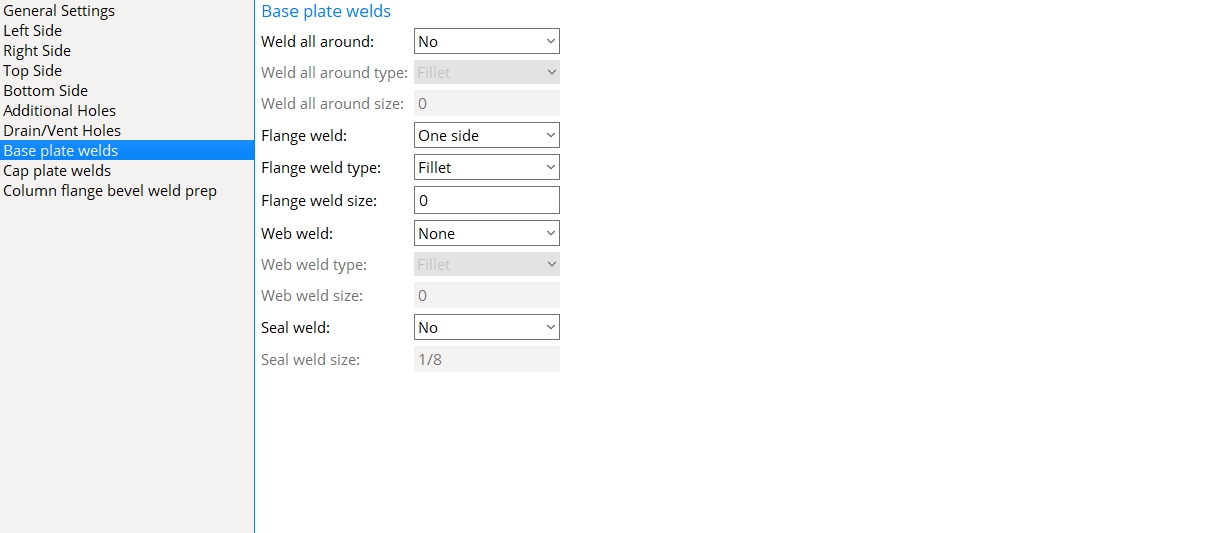
Base plate welds
When No is selected, the settings for Flange, Web, and Seal welds remain active. Welds are added to the base plate according to those particular settings.
When Yes is selected, Weld all around type and Weld all around size settings are activated and a weld is added to the base plate according to those settings. The settings are Flange, Web, and Seal welds are deactivated.
Weld all around type: Fillet or Square Groove.
| symbol | name | related options on this page |
|
|
fillet | The Weld all around size is applied. |
|
|
square groove | The Weld all around size is deactivated. |
Weld all around size: The cross-sectional leg length of a fillet weld. An entry of 0 results in a weld size that is greater than or equal to the Minimum for job and less than or equal to the Maximum for non strength connections. An entry made here that is greater than the Maximum for non strength connections will be the actual weld size applied to the base plate.
Flange weld: None or One side or Both sides.
None specifies that no flange welds are generated.
One side results is a total of three welds on a wide flange column: two on the inner flange faces of one flange and the third on an outer flange face of the other flange. For an HSS rectangular column, only the outer faces of the column's "flanges" are welded to the column plate.
Both sides for a wide flange column results in the inner faces and outer faces of both flanges being welded to the column plate. For pipe and tube columns, the results are the same as if One side was selected.
Flange weld type: Fillet or Square Groove or Bevel Groove.
| symbol | name | related options on this page |
|
|
fillet | The Flange weld size that is entered is applied. |
|
|
square groove |
Flange weld size is deactivated. A column Material setback sets the root opening of the weld to be one half the wall thickness of an HSS rectangular column. A square groove weld is only applicable to tube and pipe columns. If you apply a base plate with this weld to a column other than tube/pipe, you will receive a green banner in your information section, "Square groove welds not allowed on non-hollow section" |
|
|
bevel groove | Flange weld size is deactivated. |
Flange weld size: The cross-sectional leg length of a fillet weld. An entry of 0 results in a weld size that is greater than or equal to the Minimum for job and less than or equal to the Maximum for non strength connections. An entry made here that is greater than the Maximum for non strength connections will be the actual weld size applied to the base plate.
None specifies that no web welds are generated.
Both sides results in welds on both sides of a wide flange web. For a tube column, outer faces of the top and bottom walls are welded to the base plate.
Web weld type: Fillet or Square Groove.
| symbol | name | related options on this page |
|
|
fillet | Lets you enter a Web weld size. |
|
|
square groove |
Web weld size is deactivated. A column Material setback sets the root opening of the weld to be one half the wall thickness of an HSS rectangular column. A square groove weld is only applicable to tube and pipe columns. If you apply a base plate with this weld to a column other than tube/pipe, you will receive a green banner in your information section, "Square groove welds not allowed on non-hollow section" |
Web weld size: The cross-sectional leg length of a fillet weld. An entry of 0 results in a weld size that is greater than or equal to the Minimum for job and less than or equal to the Maximum for non strength connections. An entry made here that is greater than the Maximum for non strength connections will be the actual weld size applied to the base plate.
No specifies that no seal weld is generated.
Yes adds weld to the thickness edges and fillets of a wide flange column. For an HSS column, a seal weld is added to the HSS corners.
Seal weld size: The size applied to seal welds on base plates. The default value is set by Home > Project Settings > Job > Design > Weld Design Settings > Seal weld size.

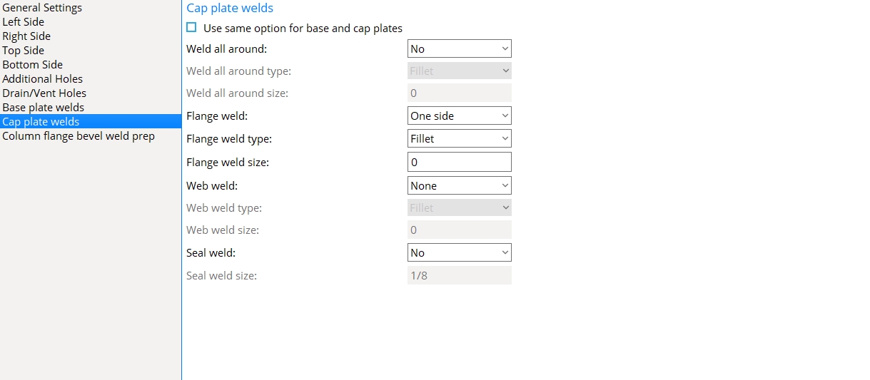
Cap plate welds
Use same option for base and cap plates: or
When unchecked (
When checked (
When No is selected, the settings for Flange, Web, and Seal welds remain active. Welds are added to the cap plate according to those particular settings.
When Yes is selected, Weld all around type and Weld all around size settings are activated and a weld is added to the cap plate according to those settings. The settings are Flange, Web, and Seal welds are deactivated.
Weld all around type: Fillet or Square Groove.
| symbol | name | related options on this page |
|
|
fillet | The Weld all around size is applied. |
|
|
square groove | The Weld all around size is deactivated. |
Weld all around size: The cross-sectional leg length of the fillet weld. An entry of 0 results in a weld size that is greater than or equal to the Minimum for job and less than or equal to the Maximum for non strength connections. An entry made here that is greater than the Maximum for non strength connections will be the actual weld size applied to the base plate.
Flange weld: None or One side or Both sides.
None specifies that no flange welds are generated.
One side results is a total of three welds on a wide flange column: two on the inner flange faces of one flange and the third on an outer flange face of the other flange. For an HSS rectangular column, only the outer faces of the column's "flanges" are welded to the column plate.
Both sides for a wide flange column results in the inner faces and outer faces of both flanges being welded to the column plate. For pipe and tube columns, the results are the same as if One side was selected.
Flange weld type: Fillet or Square Groove or Bevel Groove.
| symbol | name | related options on this page |
|
|
fillet | The Flange weld size that is entered is applied. |
|
|
square groove |
Flange weld size is deactivated. A column Material setback sets the root opening of the weld to be one half the wall thickness of an HSS rectangular column. A square groove weld is only applicable to tube and pipe columns. If you apply a cap plate with this weld to a column other than tube/pipe, you will receive a green banner in your information section, "Square groove welds not allowed on non-hollow section" |
|
|
bevel groove | Flange weld size is deactivated. |
Flange weld size: The cross-sectional leg length of a fillet weld. An entry of 0 results in a weld size that is greater than or equal to the Minimum for job and less than or equal to the Maximum for non strength connections. An entry made here that is greater than the Maximum for non strength connections will be the actual weld size applied to the cap plate.
None specifies that no web welds are generated.
Both sides results in welds on both sides of a wide flange web. For a tube column, outer faces of the top and bottom walls are welded to the cap plate.
Web weld type: Fillet or Square Groove.
| symbol | name | related options on this page |
|
|
fillet | Lets you enter a Web weld size. |
|
|
square groove |
Web weld size is deactivated. A column Material setback sets the root opening of the weld to be one half the wall thickness of an HSS rectangular column. A square groove weld is only applicable to tube and pipe columns. If you apply a cap plate with this weld to a column other than tube/pipe, you will receive a green banner in your information section, "Square groove welds not allowed on non-hollow section" |
Web weld size: The cross-sectional leg length of a fillet weld. An entry of 0 results in a weld size that is greater than or equal to the Minimum for job and less than or equal to the Maximum for non strength connections. An entry made here that is greater than the Maximum for non strength connections will be the actual weld size applied to the cap plate.
No specifies that no seal weld is generated.
Yes adds weld to the thickness edges and fillets of a wide flange column. For an HSS column, a seal weld is added to the HSS corners.
Seal weld size: The size applied to seal welds on cap plates. The default value is set by Home > Project Settings > Job > Design > Weld Design Settings > Seal weld size.
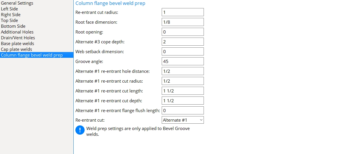
Column flange bevel weld prep
Re-entrant cut radius:The distance from the web to where the re-entrant cut intersects with the flange. This applies only when Alternate #3 is selected as the Re-entrant cut.
|
r = re-entrant cut radius. |
Root face dimension: The distance that defines how much of the flange is clipped.

|
t = root face dimension. |
Root opening: The distance of the flange setback from the surface of the connecting material.
|
o = root opening. |
Alternate #3 cope depth: A distance.
|
d = alternate 3 cope depth. |
Web setback dimension: The distance from the beam web to the surface of the connecting material.
Groove angle: A number of degrees (0 to 90) specifying the angle at which the flange is clipped.
|
Groove angle = 45 |
Alternate #1 re-entrant hole distance: A distance.
|
h = Alternate #1 re-entrant hole distance. |
Alternate #1 re-entrant cut radius: A distance.
|
r = Alternate #1 re-entrant cut radius. |
Alternate #1 re-entrant cut length: A distance.
|
l = Alternate #1 re-entrant cut length. |
Alternate #1 re-entrant cut depth: A distance.
|
d = Alternate #1 re-entrant cut depth. |
Alternate #1 re-entrant flange flush length: A distance.
|
fl = Alternate #1 flange flush length. |
Re-entrant cut: Alternate #1 or Alternate #3. This and other column flange prep options on this window are enabled only when Flange weld type is set to Bevel Groove.
|
|
Alternate #1 creates the column flange prep using the Alternate #1 re-entrant cut radius and Alternate #1 re-entrant cut length and Alternate #1 re-entrant cut depth and Alternate #1 flange flush length that are entered on this window. Alternate 1 is the default choice, per AISC specifications.
Alternate #3 creates the column flange prep using the Re-entrant cut radius that is entered on this window. The alternate 3 "rat hole" is a circle that is offset from the column flange by the Alternate #3 cope depth dimension.


|
|
OK (or the Enter key) closes this screen and applies the settings.
Cancel (or the Esc key) closes this screen without saving any changes.
Reset undoes all changes made to this screen since you first opened it. The screen remains open.
- Red or yellow exclamation point icons

- When Rectangular is selected as the Plate Type, You can use Left Side, Right Side, Top Side, and Bottom Side options to define an L-shaped, X-shaped, or T-shaped plate.
-
When Round is selected as the Plate Type, Round Plate Holes appears on the options selection list.
-
Hole Type must be set to Anchor bolt in order for the plate holes to be automatically dimensioned when the Dimension anchor bolt layout option is selected during erection view detailing.
- A user base/cap plate on top of or under a beam or joist will automatically be rotated so that its Length is parallel with the length of the beam or joist. Click here and here for contrasting examples.
- If your current Fabricator is not the Master Fabricator, any Plate schedule number that is currently or subsequently entered to the Column Edit window will continue to reference the version of this window that is set up in the Master Fabricator. This ensures that all user base/cap plates come from a single setup source, regardless of your current Fabricator.
- User base/cap plates (Connection Specifications and more)
- Plate schedule number (Connection type)
- Existing material (to add a plate definition as a miscellaneous member or material)
- Auto Standard Connections window (Project Settings)
- User Defined Connections (Project Settings)
- Change base/cap plate weld pattern (Change Options)
- Status Display (Connection type > Column base or cap plate)

