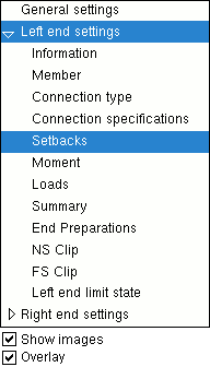
The Beam Review window ( Modeling )

The navigation tree is contained in the left pane of the Beam Review window. It makes navigating the window easier. Right-click opens a menu with options to " Expand all " and " Collapse all ."

Selecting a section name causes the settings in that section to be shown on the Beam Review window. In the example at left, " Setbacks " is selected and, as a result, the " Setbacks " leaf is expanded (as opposed to collapsed) ( VIDEO1 ). Sections are scrolled to when opened or, if they are already open, when double-clicked ( VIDEO2 ).

To resize the pane containing the navigation tree drag its right edge.

" Show images " (when checked) lets you see drawings that depict the dimensions that are controlled by connection design locks . ( VIDEO3 )

" Overlay " (when checked) displays one section at a time, just like selecting a tab on a window with tabs displays only the section for that one tab.


General settings
  Left end settings
  Right end settings


  General settings ---------------------------------------------------------------------------------------
  Section size   Composite design   Main material
  Piecemark   Slab width   Marked for processing
  Piecemark group   Number of studs   Marked for detailing
  Steel grade   Beam rotation   Node-match job
  Surface Finish   Hold rotations   Model complete
  Sequence   Rolling operation   Complete date
  Long side   Mid-ordinate   WP to WP length: plan
  Toe direction   Included angle   WP to WP length: actual
  Configuration   Rolling radius
  Long leg   Spiral offset
  Double material   Swap member ends
  Center material   Break apart
  Welded section  
ABM options apply to a beam's " Section size " -- the beam's main material.

Left end settings
Right end settings

General settings
    Left/Right end settings
        Information


Connection Changed Message   Connection Failure Message
  Connection:   Connection:
 
context-sensitive help

General settings
    Left/Right end settings
        Member


  Member ------------------------------------------------------------------------------------------------------
  End elevation   Standard detail
  Web rotation  

General settings
    Left/Right end settings
        Information
        Member
        Connection type


  Connection type ----------------------------------------------------------------------------------------
  Input connection type   Use a safety erection seat
  User defined connection   Location of safety erection seat
  Embed schedule entry   Safety erection seat gap
  System designed connection   Attachment
  NM bolt type to supported  

  NM bolt type to supporting

  Provide minimum cope depth
  NM bolt diameter   Minimum setup connection
  Use miscellaneous plates list   Disable framing situation checks

General settings
    Left/Right end settings
        Information
        Member
        Connection type
        Connection specification


  Connection specifications ---------------------------------------------------------------------------
Clip angle
Bent plate
End plate
Shear
Seated beam connection
Splice plate

General settings
    Left/Right end settings
        Member
        Connection type
        Connection specifications
        Setbacks

  Setbacks -----------------------------------------------------------------------------------------------------
  Field clearance   Connection setback
  Input minus dimension   Input material setback
  Automatic minus dimension Automatic material setback
 

General settings
    Left/Right end settings
        Information
        Member
        Connection type
        Connection specifications
        Setbacks
        Moment


  Moment -------------------------------------------------------------------------------------------------------
  Moment type   Location
  Design for doublers   Bolt pattern
  Design for stiffeners   Bolt type
  Column web doubler side   Bolt diameter
  Connection material    Re-entrant cut
  Connection type   Groove angle
  Use inner flange plates   Haunch location
  End plates  

General settings
    Left/Right end settings
        Member
        Connection type
        Connection specifications
        Setbacks
        Moment
        Loads

  Loads --------------------------------------------------------------------------------------------------------
  Shear load   Tension load
  Story shear   Compression load
 Moment load  
 

General settings
    Left/Right end settings
        Member
        Connection type
        Connection specifications
        Setbacks
        Moment
        Loads
        End preparations

  End preparations ------------------------------------------------------------------------------------------
  End-cut type   Moment connection web setback
  Web cut angle   Top flange operation
  Flange cut angle   Bottom flange operation
 

General settings
    Left/Right end settings
        Information
        Member
        Connection type
        Connection specifications
        Setbacks
        Moment
        Loads
        Summary
        End preparations
        Connection Design Locks
        ( non-moment )

Tip: Connection design locks may also be found on an edit window for a connection component .


Non-Moment Beam Connections
      NS Clip / FS Clip ( moment connection components may have been added )
      Beam Web Doubler ( values of ' 0 ' if no web doublers are designed )
      Web Extension Plate
      Welded Tee
      Bent Plate ( moment connection components may have been added )
      End Plate ( moment connection components may have been added )
      Shear Tee
      Shear Tab ( moment connection components may have been added )
      Tab Clips and Copes
      Paddle Plate for HSS Beam
      Safety Seat ( non-moment beam-to-column connections except beam seats )
      Column Reinf Plate ( may also apply to welded moment connections )
      Stability Plate ( extended shear tab to a column web )
      Shear Thru Plate On [mem num] [end]
      Seated Tee
      Seated Plate
      Seated Angle
      Web Stability Angle
      Top Flange Stability Angle
      Web Plate ( beam splice -- moment connection components can be added )
      Web Fill Plate ( values of ' 0 ' if no fill plates are designed )

General settings
    Left/Right end settings
        Information
        Member
        Connection type
        Connection specifications
        Setbacks
        Moment
        Loads
        Summary
        End preparations
        Connection Design Locks
        ( moment )
Moment Connections
      Moment End Plate
      Bolts ( end plate moment bolts )
      Moment Stiffeners ( for a moment end plate )
      Top/Bottom Moment Haunch Stiffener ( moment end plate, Eurocode )
      Top/Bottom Moment Plate ( to a web or flange )
      Top/Bottom Moment Plate ( welded moment, to a web, shear tab )
      Top/Bottom Moment Angle ( flange )
      Moment Cap Plate ( welded moment, to top of column flange )
      Column Web Doublers ( moment )
      Column Flange Stiffeners ( opposite to moment connection )
      Moment Stiffeners ( moment end plate )
      Moment Flange Plate ( beam splice )
      Inner Flange Filler Plates ( beam splice )
      Welds ( fully welded moment connection )

General settings
    Left/Right end settings
        Member
        Connection type
        Connection specifications
        Setbacks
        Moment
        Loads
        Summary
        End preparations
        Connection design locks
        Limit state

  Left/Right end limit state --------------------------------------------------------------------------

--- The capacity of a connection is calculated for various limit states during connection design and reported in the limit state table.

--- Connection design takes place in a full-featured SDS2 program , but not in SDS2 Site Planning.

--- You can review the results of connection design by reviewing connection design locks , by outputting a Connection Design Calculations Report or the Expanded Connection Design Calculations , or by visual inspection of the model.


General settings
    Left/Right end settings
        Member
        Connection type
        Connection specifications
        Setbacks
        Moment
        Loads
        Summary
        End preparations
        Connection design locks
        Limit state
        Components

  Components -----------------------------------------------------------------------------------------------

--- Custom component settings will appear on the Beam Review window only if a custom component has been added in a full-featured SDS2 program . You cannot add a custom component in SDS2 Site Planning.

--- Names of custom components whose settings may appear on a Beam Review window are " Safety Holes ," " Safety Tabs ," " Beam Outrigger ," " Beam Stiffeners ," " Reduced Beam Section " and " HSS Cap Plates ."


To open the Beam Review window :

Also see :

page 1 | contents | model > member | top