 Display Options ( Modeling > press d d )
Tool summary :
The Display Options window :
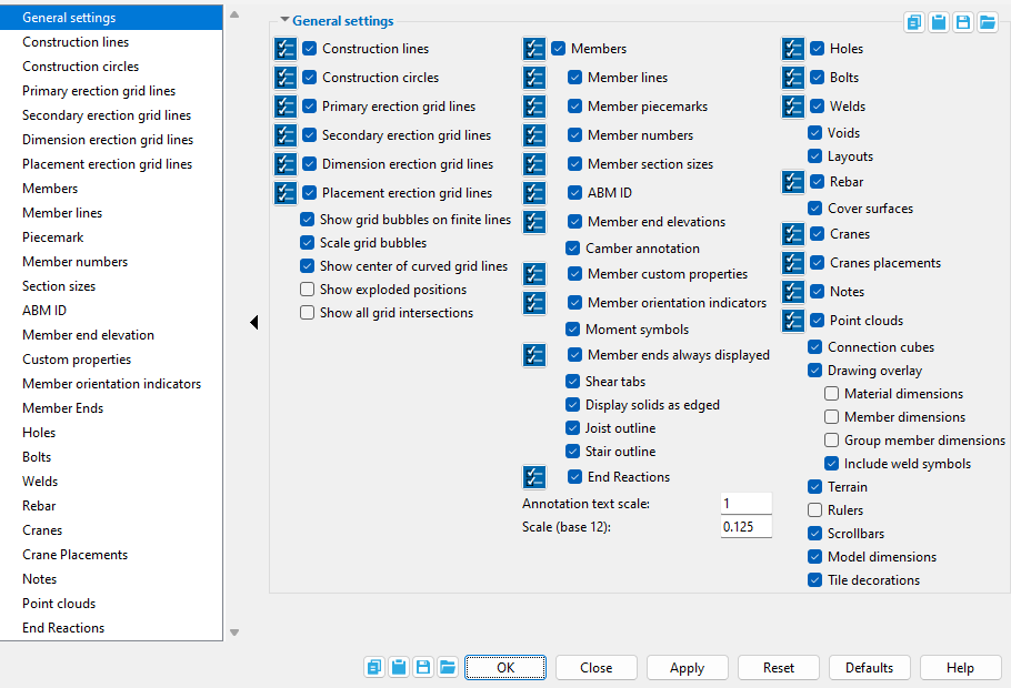
Display filters are available for certain "
General settings " options when they are checked ("
Option"). When display filters for an option are non-default, that option turns red .
When an option is red (" To access the display filters for a particular option, select that option in the tree. In this example, " Members " is selected in the tree. When that option is deselected in the tree, the display filters are no longer shown, but the filters still apply to the display of items in the model. An option is listed in the tree only if that option is checked ("
To change these settings :
Also see :
- Status Display (select ' masked ' and ' none ' to isolate)
- Depth Checking (was on this window before v2020)
- Isolate Member (alternative to turning item display off)
- Find Material (alternative to turning item display off)
Please note :
Most options on this window are either checked (
) by default. When you change an option to unchecked (or to checked), your change remains in effect as you Open different views. Selections made to this window also remain in effect when you Exit Modeling then start up again.
One option that works in an entirely different manner is " Drawing scale ," which applies to your current view only. A drawing scale change is lost when you Open a different view.
To see how making a change on this window affects your current view, press the " Apply " button, thus causing the view to redraw.
page 1 | contents | view > | view | display (index) | top
![]() Step-by-step instructions :
Step-by-step instructions :
1 . While in any Modeling view, invoke Display Options using any one (1) of the following methods:
Method 1 : Click the Display Options icon, which is pictured above. The icon can be taken from the group named ' View ' and placed on a toolbar (classic) or the ribbon (lightning).
Method 2 : If " Modeling layout style " is ' Classic ', you can use the menu system to choose View > Display Options.
Method 3, 4 or 5 : Display Options can also be configured to be invoked using a keyboard shortcut , the context menu , or a mode . For the lightning interface, this configuration is done using Customize Interface . The default keyboard shortcut for Display Options is d d .
2 . This window (the Display Options window) opens.
2a : Select which options that you want displayed in Modeling views. Turning off the display of an item does not erase that item. The item still exists as a part of the 3D model . The item is simply not displayed in the view. How to further refine which items you want to display by using display filters is explained at the top of the page.
2b (optional) : You can see the effect on the model of changing many of these options by pressing the " Apply " button.
2c : Press " OK " to close this window. Go to step 3.
3 . The window closes. Your current view redraws so that any changes you have made on the window are applied to the 3D model.
With the exception of two options (" Depth checking " and " Drawing scale "), all Display Options remain in effect from the first redraw, and as you change from view to view. They will also remain in effect if you Exit Modeling then start up Modeling again.
" Depth checking " and " Drawing scale " apply to your current view only.
page 1 | contents | view > | view | display (index) | top
If this box is checked (
If the box is not checked (
Display filters set the types of construction lines that will be shown when " "Finite" and "Infinite" explained: Finite line ( Construction Line Edit window)
"Colors" explained: Pen color ( Construction Line Edit window)
If this box is checked (
If the box is not checked (
Display filters set the colors of construction circles that will be shown when "
"Colors" explained: Pen color ( Construction Line Edit window)
Primary erection grid lines: ![]() or
or ![]() . This applies to both curved grid lines and straight grid lines .
. This applies to both curved grid lines and straight grid lines .
|
| Erection view line = grid line. A primary straight grid line is one whose " Erection view type " is ' Primary '. A primary curved grid line is one whose " Erection view type " is ' Primary '. |
If this box is checked (
If the box is not checked (
Display filters are, by default, all selected, resulting in all primary grid lines being displayed when " Deselecting certain filters prevents certain grid lines from being displayed. For example, deselecting the grid lines named SECOND FLOOR, ROOF FRAMNG and MEZZANINE prevents those grid lines from being displayed in your current view and in views that you subsequently Open . Pressing the " "Curved" explained: Grid lines (topic).
"Finite" and "Infinite" explained: Finite ( Edit Erection View )
"Colors" explained: Grid line pen color ( Edit Erection View )
"Line type" explained: Grid line type ( Edit Erection View )
"Name" explained: View name ( Edit Erection View )
Secondary erection grid lines: Same as " Primary erection grid ines ," except that this applies to the display of secondary straight grid lines or secondary curved grid lines.
Dimension erection grid lines: Same as " Primary erection grid lines ," except that this applies to the display of dimension only straight grid lines or dimension only curved grid lines.
Placement erection grid lines: Same as " Primary erection grid lines ," except that this applies to the display of placement only straight grid lines or placement only curved grid lines.
Show grid bubbles on finite erection views: ![]() or
or ![]() . This applies to finite straight grid lines ("
. This applies to finite straight grid lines (" ![]() Finite ") and to curved grid lines .
Finite ") and to curved grid lines .
|
If this box is checked (
If the box is not checked (
Scale grid bubbles: ![]() or
or ![]() . This applies to finite straight grid lines and to curved grid lines .
. This applies to finite straight grid lines and to curved grid lines .
|
If this box is checked (
If the box is not checked (
Show center of curved grid lines: ![]() or
or ![]() .
.
|
|
|
Tip: Regardless of the choice made here, the center of a curved grid line is an exact point . |
If this box is checked (
) in your current view and in views that you subsequently Open .
If the box is not checked (
Show exploded positions: ![]() or
or ![]() . This option will cause members to be displayed in different locations in your current view only if the user of a full-featured SDS2 program has set exploded view positions for members in your current erection view.
. This option will cause members to be displayed in different locations in your current view only if the user of a full-featured SDS2 program has set exploded view positions for members in your current erection view.
When this box is checked (
If the box is not checked (
Tip: If all you want to do is double check the exploded positions of members, select this option then use the " Apply " button to see what you get, then deselect this option and press " OK ." Members will be redrawn in their actual 3D positions and all Modeling tools will be enabled.
Show all grid intersections: ![]() or
or ![]() . This applies to isometric views of the model.
. This applies to isometric views of the model.
When this box is checked (
If the box is not checked (
page 1 | contents | view > | view | display (index) | top
Depth checking: ![]() or
or ![]() . Unlike all other options on this window except " Drawing Scale ," " Depth Checking " only affects your current view. Any change made here is lost when you exit your current view.
. Unlike all other options on this window except " Drawing Scale ," " Depth Checking " only affects your current view. Any change made here is lost when you exit your current view.
|
When this box is checked (
When the box is not checked (
Tip 1: You can place depth check controls onto your tool bar using tool bar configuration options . If you do so, you can change depth checking from your tool bar instead of having to open the Display Options window (this window).
Tip 2: A keyboard shortcut or mouse binding can be applied (in Modeling ) to " Toggle Depth Checking ." The tool can be found in the " Miscellaneous " group on the Keyboard Shortcut Editor window or the Mode Configuration window.
page 1 | contents | view > | view | display (index) | top
Members: ![]() or
or ![]() . This applies all members, regardless of whether they are in stick form or in any of the three solid forms .
. This applies all members, regardless of whether they are in stick form or in any of the three solid forms .
|
If this box is checked (
If the box is not checked (
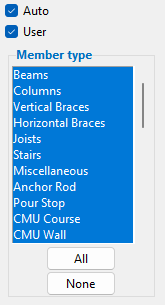
Display filters are, by default, all selected, resulting in all members not hidden by other options on this window being displayed when " Deselecting certain filters prevents certain members from being displayed. For example, deselecting the member type ' Miscellaneous ' hides all miscellaneous members that are in your current view and in views that you subsequently Open . Pressing the " "Existing" explained: " Existing member " (press " Status " on a member window > Member Status Review > )
"Sequence" explained: " Sequence " (field for selecting a member's sequence, various member windows).
"Zone" explained: Zone and Sequence Options (setup window).
"Member type" explained: Model > Member > Review (lists many member types)
"Member number" explained: Member numbers (topic)
Member lines: ![]() or
or ![]() . This applies to members in stick form .
. This applies to members in stick form .
If this box is checked (
If the box is not checked (
Display filters are, by default, all selected, resulting in member lines being displayed when " Deselecting certain filters prevents certain member lines from being displayed. For example, deselecting the member type ' Vertical braces ' hides all vertical brace member lines that are in your current view and in views that you subsequently Open . Pressing the " "Member lines" explained: Member lines . (topic)
"Existing" explained: " Existing member " (press " Status " on a member window > Member Status Review > )
"Sequence" explained: " Sequence " (field for selecting a member's sequence, various member windows).
"Zone" explained: Zone and Sequence Options (setup window).
"Member type" explained: Model > Member > Review (lists many member types)
"Member number" explained: Member numbers (topic)
Member piecemarks: ![]() or
or ![]() . If a member has not yet been assigned a piecemark, then member numbers are displayed instead of piecemarks .
. If a member has not yet been assigned a piecemark, then member numbers are displayed instead of piecemarks .
If this box is checked (
If the box is not checked (
Display filters are, by default, all selected, resulting in member piecemarks being displayed when " Deselecting certain filters prevents certain member piecemarks from being displayed. For example, unchecking the box for " Pressing the " "Piecemarks" explained: Piecemarks (topic)
"Existing" explained: " Existing member " (press " Status " on a member window > Member Status Review > )
"Sequence" explained: " Sequence " (field for selecting a member's sequence, various member windows).
"Zone" explained: Zone and Sequence Options (setup window).
"Member type" explained: Model > Member > Review (lists many member types)
"Member number" explained: Member numbers (topic)
If this box is checked (
If the box is not checked (
Member section sizes: ![]() or
or ![]() . This applies to members of all types, including beams, columns, braces, miscellaneous members and custom members. For miscellaneous members, the display of the " Description " of each member's " Main member material " is controlled by this option.
. This applies to members of all types, including beams, columns, braces, miscellaneous members and custom members. For miscellaneous members, the display of the " Description " of each member's " Main member material " is controlled by this option.
If this box is checked (
If the box is not checked (
Note: section sizes will be displayed with a non-standard annotation if the member's " Steel grade " has a non-standard annotation specified on its material grade setup window and the option "
Custom member section sizes: Not all custom members can have their section sizes displayed. The plugin for a custom member must include the GetSectionSize method in order for the section size of that custom member to be displayed.
ABM ID: ![]() or
or ![]() . The main material of a member may be assigned an ABM ID when a new ABM is created in a full-featured SDS2 program.
. The main material of a member may be assigned an ABM ID when a new ABM is created in a full-featured SDS2 program.
If this box is checked (
If the box is not checked (
Member end elevations: ![]() or
or ![]() . This applies to plan views when " Show elevation on member " in Erection View Detailing Defaults ( Fabricator Setup ) is set to ' Reference '. It applies to plan views, elevation views and isometeric views when " Show elevation on member " is set to ' Absolute '.
. This applies to plan views when " Show elevation on member " in Erection View Detailing Defaults ( Fabricator Setup ) is set to ' Reference '. It applies to plan views, elevation views and isometeric views when " Show elevation on member " is set to ' Absolute '.
For this example, " Show elevation on member " was set to ' Reference '. The displayed value of (+9 1/2) is the offset of the member work point from the reference elevation of the plan view.
For this example, " Show elevation on member " was set to ' Absolute '. Since both ends of the member are at an elevation of 114-6 , the value is shown in the middle of the member. If this box is checked (
If the box is not checked (
If this box is checked (
If the box is not checked (
Note: To get a camber annotation, the " Rolling operation " must be set to ' Camber annotation ' or to ' Camber (Both) ' and the " Mid-ordinate " must be a value other than ' 0 ' (zero).
Member custom properties: ![]() or
or ![]() .
.
If this box is checked (
If the box is not checked (
Setup: Erection View Member Labels
Member orientation indicators: ![]() or
or ![]() . This applies (after you press " OK " or " Apply ") to members in stick form in Modeling that are in plan views and elevation views. In isometric views where the member orientation indicators cannot be drawn at right angles, member orientation indicators are never displayed.
. This applies (after you press " OK " or " Apply ") to members in stick form in Modeling that are in plan views and elevation views. In isometric views where the member orientation indicators cannot be drawn at right angles, member orientation indicators are never displayed.
If this box is checked (
If the box is not checked (
Display filters are, by default, all selected, resulting in member orientation indicators being displayed when " Deselecting certain filters prevents certain orientation indicators from being displayed. For example, unchecking the box for " Pressing the "
Moment symbols: ![]() or
or ![]() . This applies to beams with moment connections that are displayed in stick form .
. This applies to beams with moment connections that are displayed in stick form .
If this box is checked (
If the box is not checked (
Member ends always displayed: ![]() or
or ![]() . This applies all members, regardless of whether they are in stick form or in any of the three solid forms .
. This applies all members, regardless of whether they are in stick form or in any of the three solid forms .
If this box is checked (
If the box is not checked (
Display filters set, by end attribute, which member ends will be shown when "
"Left end" and "Right end" explained: Determining left end & near side (topic)
Shear tabs: ![]() or
or ![]() .. This applies to plan views when beams with single-plate shear connections are displayed in stick form .
.. This applies to plan views when beams with single-plate shear connections are displayed in stick form .
If this box is checked (
If the box is not checked (
If this box is checked (
If the box is not checked (
Topic: Terrain
User and Site Options: Modeling > " Modeling background color 1 " and " Modeling background color 2 "
Setup: " Top of terrain " ( enabled in SDS2 review stations)
Setup: " Thickness of terrain " ( enabled in SDS2 review stations)
If this box is checked (
If the box is not checked (
Joist outline: This applies to joists in stick form .
If this box is checked (
If the box is not checked (
Stair outline : This applies to stairs in stick form .
| YouTube video: Stair Member Line .
(Recorded in SDS2 Detailing , v2020i) |
If this box is checked (
If the box is not checked (
HOW/2: STAIR MEMBER LINE
Point Location: Stair Exact Point
Topic: Work lines (member lines)
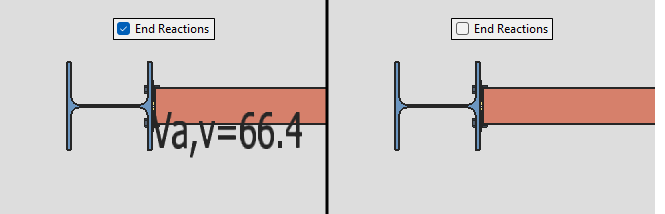
If this box is checked (
Loads " leaf are shown at the respective member end.
If the box is not checked (
End Reactions " is red, then the filters are not in their default state. In other words, red indicates that some filters have been deselected.
Display filters set which end reactions will be shown and which member type(s) show them when "
Auto ," then only "
Setup: Home > Project Settings > Fabricator > Detailing > Erection View Member Labels > Label Positioning
Setup: Home > Project Settings > Fabricator > Detailing > Erection View Member Labels > Reaction Nomenclature
Annotation text scale: The scale of the point location annotation text. This scale applies to the dimension that is shown when you locate a second point with ANNO turned on. The scale also applies to the text that identifies the operative snap mode and to the dimension labels for " Model dimensions ."
Example 1: An " Annotation text scale " of ' 1 ' is the default. If you double the " Annotation text scale ," the text will be twice as high and twice as wide. Be aware that the text always stays this same size, regardless of how much you zoom in or zoom out .
Example 2: If you double the " Scale " of your current view (e.g., from 0.125 to 0.25), the annotation text is halved since the same number of pixels will now equal twice the distance. You would need to double the " Annotation text scale " if you wanted to make the annotation text be the size that is was before you doubled the " Scale ."
Note: This setting applies to your workstation only. It applies across different views in Modeling and different drawings in the Drawing Editor . It is not tied to the view or drawing that you are in. In Modeling , this means that no matter what view you open, the " Annotation text scale " will remain the same.
Scale (base 10 or base 12): The scale at which an erection view drawing of your current erection view will be detailed (in a full-featured SDS2 program ) for the first time. This option also affects the letter sizes of piecemarks and section sizes relative to the materials in your current view (but does not affect their actual printed size, which is set in Drawing Presentation ). Any change to this field will be lost when you exit your current view.
If this box is checked (
If the box is not checked (
Display filters are, by default, all selected, resulting in all categories of holes having the potential to be displayed when " Deselecting certain filters prevents certain holes from being displayed. For example, unchecking the box for " Pressing the " "3D holes" explained: 3D holes (topic)
"System" explained: Holes created during the Creating 3D material or Matching holes phases of Process and Create Solids .
"User" explained: User-added holes or user-modified system holes.
"Thru" explained: " Hole depth " is ' Thru ' ( Hole Edit window)
"Blind" explained: " Hole depth " is ' Blind ' ( Hole Edit window)
"Diameter" explained: " Hole diameter " ( Hole Edit window)
"Slot length" explained: " Slot length " ( Hole Edit window)
"Type" explained: " Hole type " ( Hole Edit window)
"Machine/Tool operations" explained: " Head type " and " Threads " ( Hole Edit window)
If this box is checked (
If the box is not checked (
Display filters are, by default, all selected, resulting in all categories of bolts potentially being displayed when " Deselecting certain filters prevents certain bolts from being displayed. For example, unchecking the box for " Pressing the " "3D bolts" explained: 3D bolts (topic)
"Shop" and "Field" explained: Class " ( Bolt Edit window)
" TC" and " No TC" explained : " Tension control (TC) " ( Bolt Edit window)
"Diameter" explained: " Diameter " ( Bolt Edit window)
"Length" explained: " Bolt length " ( Bolt Edit window)
"Grade" explained: " Bolt type " ( Bolt Edit window)
Welds: ![]() or
or ![]() . This applies to 3D weld s on members in a solid form .
. This applies to 3D weld s on members in a solid form .
If this box is checked (
If the box is not checked (
Display filters set, by weld attribute, which welds will be shown when "
"Shop" and "Field" explained: " Weld class " ( Edit Weld window)
"Size" explained: " Size " ( Edit Weld window)
"Type" explained: " Type " ( Edit Weld window)
Voids: ![]() or
or ![]() . Voids remove material from members. This applies when voids exists in your current Job and members are displayed in a solids form .
. Voids remove material from members. This applies when voids exists in your current Job and members are displayed in a solids form .
If this box is checked (
If the box is not checked (
Note: Turning off the display of voids does not stop them from removing materials. To stop voids from removing materials, the voids need to be deleted, which is something that you cannot do in an SDS2 review station.
Layouts: ![]() or
or ![]() . Concrete walls and concrete slabs that are displayed in a solids form have white reference lines that shows the member's layout. This can also apply to other custom members that may be in your current Job .
. Concrete walls and concrete slabs that are displayed in a solids form have white reference lines that shows the member's layout. This can also apply to other custom members that may be in your current Job .
If this box is checked (
If the box is not checked (
Note: Locate options such as INCM snap to the layout . The layout coincides with the member's member line but is a distinct entity.
Rebar: ![]() or
or ![]() . This applies when rebar exists in your current Job and members are displayed in a solids form .
. This applies when rebar exists in your current Job and members are displayed in a solids form .
If this box is checked (
If the box is not checked (
Cover surfaces: ![]() or
or ![]() . This applies when cover surfaces exists in your current Job and members are displayed in a solids form .
. This applies when cover surfaces exists in your current Job and members are displayed in a solids form .
If this box is checked (
If the box is not checked (
Cranes: ![]() or
or ![]() . If a crane has been added to your current Job , you can display it (or not) using this option.
. If a crane has been added to your current Job , you can display it (or not) using this option.
If this box is checked (
If the box is not checked (
Display filters are, by default, all selected, resulting in all categories of cranes having the potential to be displayed when " Deselecting certain filters prevents certain cranes from being displayed. For example, deselecting a certain crane's name prevents that crane from being displayed. Pressing the " "Cranes" explained: Cranes & crane placements (topic)
Crane placements: ![]() or
or ![]() . If a crane placement has been added to your current Job , you can display it (or not) using this option.
. If a crane placement has been added to your current Job , you can display it (or not) using this option.
If this box is checked (
If the box is not checked (
Display filters set the names of crane placements that can potentially be shown when "
"Crane placements" explained: Cranes & crane placements (topic)
|
If this box is checked (
If the box is not checked (

Display filters are, by default, all selected, resulting in all categories of notes that are not project notes having the potential to be displayed when " Deselecting certain filters prevents certain notes from being displayed. For example, deselecting an " Approved " note prevents notes that have been set to " Approved " from being displayed. Pressing the " "Notes" explained: Notes (topic)
"Discipline" explained: " Discipline " ( Note Viewer )
"Status" explained: " Status " ( Note Viewer )
"Custom" explained: " Custom " ( Note Viewer )
Connection cubes ( new ): ![]() or
or ![]() .
.
If this box is checked (
If the box is not checked (
page 1 | contents | view > | view | display (index) | top
If this box is checked (
If the box is not checked (
|
| To make the dimensions go away, you need to hover a different material. |
|
Dimensions are not shown when this option is off ( |
| Tip: Dimensions displayed in red are dimensions that a user has manually changed on the detail -- click here for more information. | ||
Before material dimensions can be shown: Auto detailing of submaterials is required. If a submaterial detail is not up to date, or if the detail has not yet been generated, dimensions cannot be shown. Also, any member that you want to show material dimensions on must be displayed in a solid form . You cannot auto detail in an SDS2 review station -- this must be done in a full-featured SDS2 program .
If this box is checked (
) in order for that material's dimensions to be displayed. You cannot display member main material dimensions when this option is checked, unless the " Member dimensions " option is also checked. An alternative to this option is to use Show Dimensions , which keeps displaying the dimensions until you Clear Dimensions . Show Dimensions also allows you to display dimensions on more than one material.
If the box is not checked (
|
|
Dimensions are shown when " |
Before member dimensions can be shown: Auto detailing of members is required. If a member detail is not up to date, or if the detail has not yet been generated, dimensions cannot be shown. Also, the member must be displayed in a solid form . You cannot auto detail in an SDS2 review station -- this must be done in a full-featured SDS2 program .
If this box is checked (
If the box is not checked (
Group member dimensions: ![]() or
or ![]() . See " Member dimensions ." This display option works in the same way as that option, but applies to group members. Auto detailing of group members is required. You cannot auto detail in an SDS2 review station -- this must be done in a full-featured SDS2 program .
. See " Member dimensions ." This display option works in the same way as that option, but applies to group members. Auto detailing of group members is required. You cannot auto detail in an SDS2 review station -- this must be done in a full-featured SDS2 program .
Include weld symbols: ![]() or
or ![]() . This applies when "
. This applies when " ![]() Member dimensions " are shown. It may also apply when "
Member dimensions " are shown. It may also apply when " ![]() Material dimensions " are shown, though normally a weld symbol does not appear on a submaterial detail unless a user has added one. It can also apply when "
Material dimensions " are shown, though normally a weld symbol does not appear on a submaterial detail unless a user has added one. It can also apply when " ![]() Group member dimensions " are shown.
Group member dimensions " are shown.
|
If this box is checked (
If the box is not checked (
page 1 | contents | view > | view | display (index) | top
If this box is checked (
If the box is not checked (
Topic: Terrain
User and Site Options: Modeling > " Modeling background color 1 " and " Modeling background color 2 "
Setup: " Top of terrain " ( enabled in SDS2 review stations)
Setup: " Thickness of terrain " ( enabled in SDS2 review stations)
 |
Rulers shown in an elevation view. The rulers display global coordinates , expressed in the primary dimension " Units ." Rulers do not appear in isometric views, or in elevation views that are not in an X-Z or Y-Z plane. |
If this box is checked (
If the box is not checked (
Note: User and Site Options > Modeling > " Rulers active " can be used to make rulers be automatically turned on/off each time you start Modeling .
If this box is checked (
If the box is not checked (
Tip: To move the display without using scrollbars, use Pan or Translate .
Note: User and Site Options > General > " Scrollbars active " sets whether scrollbars are turned on or off for each time you start up Modeling .
Model dimensions: These are dimensions that have been added to the model using Model > Dimension > Add or the toolbar icons named Dimension Clearance or Dimension Members .
If this box is checked (
If the box is not checked (
Also see: The " Annotation text scale " that is specified on this window ( Display Options ) sets the size of a model dimension's label.
Tile decoration: ![]() or
or ![]() . Tile decorations provide a way to activate tile tools.
. Tile decorations provide a way to activate tile tools.
|
From left to right, the tile decorations in this example are " Toggle Active Tile " " Split Tile Vertically " " Split Tile Horizontally " " Single Tile " and " Four Tiles " |
If this box is checked (
If the box is not checked (
Setting the default: User and Site Options > General > " Tile decorations active " sets whether tile decorations are turned on or off when you lanch a new Modeling session.
page 1 | contents | view > | view | display (index) | top
To close this window :
"OK" (or the Enter key) closes this window and redraws your computer screen according to the selections you have made on it.
With the exception of two options ( Depth checking and Drawing scale ), all Display Options remain in effect from the first redraw, and as you change from view to view. They also remain in effect if you Exit Modeling then start up Modeling again.
"Cancel" (or the Esc key) closes the Display Options window without saving any of the changes you made to it since you originally opened it or last pressed " Apply ."
"Reset" undoes all changes that were made to the Display Options window since you originally opened it or last pressed " Apply ." The window remains open.
"Apply" redraws your computer screen to show the results of any changes you have made on this window. The window does not close, and you can make additional changes to the window before you press " OK ."
Please note that once you press " Apply ," any selections you made since you originally opened this window are saved, which means that " Reset " will no longer undo those selections.