The Status Display & Status Select windows ( Modeling )
- Status Display (to open the Status Display window)
- Status Select (to open the Status Select window)
Options :
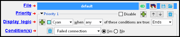
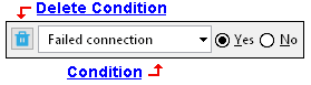
Conditions can be selected from under these categories. For example, the " Failed connection " condition (shown above), is under the " Search " category. Additional categories become available when you have an SDS2 Concrete license. See the Condition(s) list.
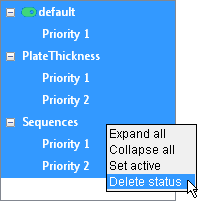
To delete a status display file from this window , right-click over that file's area in the file tree (left panel) and choose " Delete status " on the context menu. In this example, the status display file that will be removed is "Sequences." The tree shown here has files named "default" "PlateThickness" and "Sequences." If you choose " Delete status " when there is only one file, that one file will be replaced on this window by a default file. At least one file is always shown on the Status Display window. " Delete status " does not delete a file from your computer, but removes it from this window only.
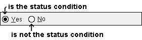
What is true ?
A status condition is true when it is able to color-code an item in the model.
Also see :
|
- Member Status Review window (status review)
- Update Attributes (status input)
- By Status Display (selection filter) (
 )
)
- Drawing Data (status input)
- Status Configuration list box (sets the active status display file without opening this window) ( )
- conf_status (contains status files you can load)
- Status display criteria ( User and Site Options > Modeling > set default status display file(s)) ( )
- Status Display check box (turns status display in the model on/off)
- Isolate Member (alternative for isolating members)
- Find Material (alternative for isolating members)
- Display Options (alternative for isolating members)
- Search Options (alternative for identifying members)
- Status Report by Detail (alternative in report form)
- Status Report by Sheet (alternative in report form)
- Status Report by Category (alternative in report form)
- Making comments & entering status data (topic)
model > | status display | status select | status (index) | top
File widgets (except for active/inactive , these affect only the file name that is shown) :
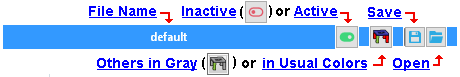
File name : The name of a status display file is shown in a banner above the priorities and conditions that are stored in that file. For example, the file name might be "default":
| default |
Multiple files may be shown on this window, each with its own banner and unique file name.
The widgets that are embedded in file's banner apply only to that file.
To remove a status display file from this window, right-click in the file tree (left panel) and choose " Delete status " as shown in the example at the top of this page. " Delete status " does not delete a file from your computer, but removes it from this window only.
You can have multiple files loaded on this window. Each will have its file name displayed in a blue banner. One (1) of these files can be your active file (
). All other files are inactive (
).
The active status display file is the file that controls status display in your current view when you press the " OK " button.
The active status display file also controls status display when you press the " Apply " button.
The summary that you get when you press the " Legend " button summarizes the contents of the active status display file.
To make a different status file into your active file, click that file's
Outside of this window, you can use the toolbar item named Status Configuration to set the active status display file.
The Status Display check box can be used outside of this window to turn status display on or off (
or
). When status display is off, the active status file will no longer affect display in the model, but it will remain active (
From this window, the " Cancel " button can be used to turn status display off. The active status display file will no longer affect display in the model. The Status Display check box will go from
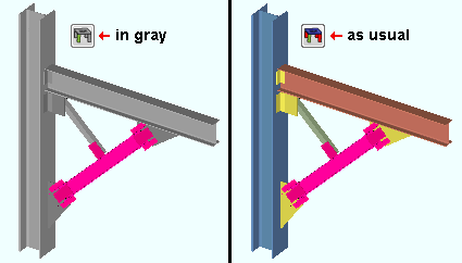
(others in gray) or
(others as usual):
VIDEO Materials that are not displayed in a status display color can be displayed in gray. (Recorded in SDS2 Detailing , v2016.)
If
If
Lets you save to a file the status information that is under a particular file name banner .
By default, the file will overwrite the contents of the original file. You can, however, instead choose to save the file to a new location and/or to give it a new name.
The " Save " button at the bottom of this window can be used to save all files on this window. The
button only lets you save one file at a time.
Lets you open a different file, which on this window will take the place of the file whose file name banner the
button you pressed is embedded in.
To open a file that will be shown in addition to the file(s) that are already shown on this window, you can press the " Load " button at the bottom of this window. That " Load " button also lets you open more than one file at a time.
model > | status display | status select | status (index) | top
Priority widgets (priority 1 is listed 1st in a file):
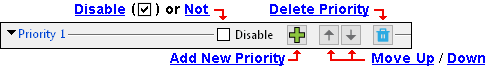
Disable:
If this box is checked (
If the box is not checked (
Creates a new priority that is, initially, an exact copy of this priority.
You can modify the new priority to suit your purposes.
Removes a priority (and all conditions stored within that priority).
This only applies when there are multiple priorities in the file. If there is only one priority in a file, then pressing the
button removes that priority and replaces it with a default priority.
This applies when there are multiple priorities in the same status display file .
moves the priority your cursor is in up.
moves the priority your cursor is in down.
The priority number changes as you move a priority up or down. Priority 1 is always the first priority in a status display file.
Changing a priority's number (position) can affect status display. See this example from the Status Display tool help page. Where conditions in different priorities are true for particular members or materials, the conditions in the higher priority (lower number) will be the conditions that control the display.
model > | status display | status select | status (index) | top
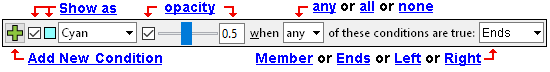
or
or etc. This sets the way that stick members and solid members/materials that meet the " Conditions " in the active status file will be displayed in the 3D model. When ' Member ' and ' any ' are selected, members for which at least one of the conditions is true will be made invisible (masked) if ' Masked ' is selected. If a color is selected, members for which at least one of the conditions is true will be displayed in that color.
Status Display can mask, color code, or isolate members. To set opacity instead of a color:
' Member ' must be selected as the type of item to be displayed.
If you uncheck ( To isolate members: Select ' Masked ' and ' none '. The members for which the " Conditions " are true will be isolated (not masked).
Note: The vertex points or exact points of members that have been masked cannot be located during operations such as Construction Line Add .
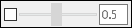
Opacity lets you make solid members translucent. It applies only when ' Member ' is the item to be displayed with the selected opacity. Also, opacity does not apply to members in stick form. The opacity of members can be set with a slider or by typing a number between 0.1 and 1.0. An opacity of 0.1 makes the status display color nearly invisible, so that you can easily see through the color-coded item. An opacity of 1.0 makes the status display color entirely opaque. Note that you can set opacity instead of a color .
VIDEO Varying degrees of opacity are set for colors in various priorities on the Status Display window, and the effect of doing so is shown in the model. (Recorded in SDS2 Detailing , v2017.)
any or all or none : This is the display logic function.

' any ' independently evaluates each of the conditions in the priority you are working in and, where at least one condition is true for a member/material in the model, causes that member or material to be displayed as specified .
' all ' evaluates each of the conditions in this priority and, where all conditions are true for a member/material in the model, causes that member or material to be displayed as specified .
' none ' is the opposite of ' any '. For example, if selecting ' any ' causes three members to be blue (when " Apply " or " OK " is pressed), then selecting ' none ' causes all members except those three members to be blue.
Note: For a priority with only one condition, ' any ' and ' all ' will give the exact same results.
Member or Ends or Left or Right . The display item that is to be color coded or etc.. ' Masked ' and ' Opacity ' are not applicable to ' Ends ' or ' Left ' or ' Right '. It should also be used for most bolt , weld , hole or material status conditions.
VIDEO The priority used to color code the entirety of members in this example is priority 3. The priorities used to color code member ends are priority 1 (left end) and priority 2 (right end). This priority order allows members for which all conditions are true to be colored by all three colors. (Recorded in SDS2 Detailing , v2018.) ' Member ' results in the entire member being color coded, masked or etc.when the status condition is true for either the left or right member end or true for the member as a whole.
' Ends ' results in both ends of the member being color coded when the status condition is true for both ends of a member or true for the member as a whole. Only one end of the member is color coded if the condition is true for only that one end of the member.
' Left ' results in the left end of the member being color coded when the status condition is true for the entire member or true for the left end of the member.
' Right ' results in the right end of the member being color coded when the status condition is true for the entire member or true for the right end of the member.
Special cases: For a bolt , weld , hole or material status condition, selecting ' Member ' results in bolts or welds or holes or materials being color coded or etc. You may not get any results when you select ' Ends ' or ' Left ' or ' Right ' for such conditions. It is generally best to select ' Member ' when you want to color code bolts, welds, holes or material.
(Add New Condition): Pressing this button adds a new condition.
The condition will be added to this priority (the priority your cursor is in) and will be a default condition. You should modify it to suit your purposes.
Conditions are independently evaluated for their truth value. Their truth value can be used to color code or mask based on whether any or all or none is selected.
model > | status display | status select | status (index) | top
A priority can have one or multiple conditions.
If there are no other conditions in the priority, then
You can select a condition from any of the following categories:
General status options >
Detailing and processing >
Approval and modeling >
Fabrication status >
Shipping and erection status >
Member status >
Group member status >
Material status >
Bolt status >
Hole status >
Weld status >
Search >
Connection type >
Connection auto loads >These categories become available when you have an SDS2 Concrete license: Concrete member >
Concrete material >
CMU material
Beam template
CMU template
Column template
Thickened slab template
Grade beam template
Continuous footing template
Rebar >
Concrete cover surfaceWithin a priority , all conditions are acted on by the same display logic . The following example has two conditions. Since ' all ' is selected, both conditions have to be true for a member in order for status display to color code that member.
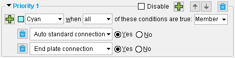
This example of a status priority would, since ' all ' is selected, color code members that have both an auto standard connection and an end plate connection. This priority would find two potentially overlapping situations:1) beams with an end plate on one end and an auto standard connection on the other. 2) beams with auto standard end plates on either end or both ends. If you were to change ' Member ' to ' Ends ', only those beam ends with auto standard end plates would be color coded cyan.
model > | status display | status select | status (index) | top
------ General status options ------
Zone: ' is / is not ' from ' a zone ' to ' a zone '. The same zone twice (e.g. 1 to 1) designates a single zone.
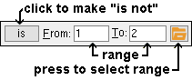
To enter a zone range: press the "file cabinet" browse button (
) to open a list of zones that have been defined on the Zone Names window in setup. On the list, select the range of zones that you want. After you press " OK " to close the list, " From " and " To " will be filled out with the first and last zones that you selected.
Example: For priority 1 in the active status display file , you enter 'is' and a particular zone range here to define the condition . You select ' Member ' as the display item, then assign a display color and choose ' any ' as the display logic function. When you press " OK ," those members in your current view that are within the zone range you entered are displayed in the color you selected.
Member display: The same members are color coded regardless of whether ' Member ' or ' Ends ' or ' Left ' or ' Right ' is selected. Both ends of those members are color coded when ' Ends ' is selected.
Member review windows: Sequence
Setup: Zone and Sequence
Status Report by XXX: Zone
Sequence: ' is / is not ' from ' a sequence ' to ' a sequence '. The same sequence twice designates a single sequence (e.g., 2 to 2).
|
To enter a sequence range, press the "file cabinet" browse button (
Example: For priority 1 in the active status display file , you enter ' is ' and a particular sequence range to define the condition . You select ' Member ' as the display item, then assign ' Masked ' as the display option and ' any ' as the display logic function. When you press " OK ," those members in your current view that are assigned a sequence within the range you designated are made invisible. It does not matter if those members are in stick or in one of the three solid forms. You might do this to hide members that have already been reviewed.
Member display: The same members are color coded regardless of whether ' Member ' or ' Ends ' or ' Left ' or ' Right ' is selected. Both ends of those members are color coded when ' Ends ' is selected.
Member review windows: Sequence
Setup: Zone and Sequence
Status Report by XXX: Sequence
Revision: ' is / is not ' from ' a number ' to ' a number '. This option is for tracking member revisions, not sheet revisions. It can track any range of " Short revision descriptions " that are currently assigned to members. The same number twice (e.g. 1 to 1) designates a single " line " number in Member Revisions setup. The first line in Member Revisions setup is line 0. A number entered here also corresponds to the order (beginning with 0) that a revision is listed on the list box ( ![]() ) for " Short revision description " in Member Status Review .
) for " Short revision description " in Member Status Review .
Example: To line 4 in Member Revisions , CO-4 is entered as the short revision description. In Member Status Review , ' CO-4 ' is entered as the " Short revision description " for two different beams. On this window, for priority 1 in the active status display file , you select a " Revision " range of ' 4 ' to ' 4 ' and ' Member ' and a color and ' any '. When you press " OK ," the two members that were assigned the CO-4 short revision description are displayed in the color you selected.
Member display: The same members are color coded regardless of whether ' Member ' or ' Ends ' or ' Left ' or ' Right ' is selected. Both ends of those members are color coded when ' Ends ' is selected.
Tip: To color code all members that users have assigned a revision to, enter " is not " from ' 0 ' to ' 0 '. This works because 0 is the default revision, and users must select a revision other than 0 to have that other revision assigned.
Setup: Member Revisions
Member Status Review: Short revision description
Reports: Member Revisions by Member , Members in Member Revisions
Status Report by XXX: Revision level
Sheet revisions: revision chart on a detail sheet
When ' Yes ' is selected, the condition is true for members that a user has put ' On hold '. A user can put a member ' On hold ' using Update Attributes or the Member Status Review window. Holding a member is usually interpreted as meaning holding a member's detail from release to the shop.
When ' No ' is selected, the condition is true for members that are not on hold.
Example: For priority 1 in the active status display file , you select " Hold status " as the a condition and select ' Yes '. You then select ' Member ' as the display item, ' Blue ' as the display item's color and ' any ' as the display logic function. When you press " OK ," any members in your current view that are on hold are displayed in the color blue. Be aware, though, that if there are other conditions in priority 1, other members that are not on hold may also be displayed in the color blue.
Member display: The same members are color coded regardless of whether ' Member ' or ' Ends ' or ' Left ' or ' Right ' is selected. Both ends of those members are color coded when ' Ends ' is selected.
Status Update: Member hold status
Member Status Review: Member hold status
Status Report by XXX: Member hold status
Reason for hold: Any string of characters. Text case does not matter (e.g. "under review" is interpreted as being the same as "UNDER REVIEW").
Example: For priority 1 in the active status display file , if a string of characters is entered for this condition and the same string is entered to " Reason for member hold " on the Member Status Review window for particular members, then (when you press " OK ") those members will be displayed in the selected display color .
Member display: The same members are color coded regardless of whether ' Member ' or ' Ends ' or ' Left ' or ' Right ' is selected. Both ends of those members are color coded when ' Ends ' is selected.
Status Update: Reason for member hold
Member Status Review: Reason for member hold
Status Report by XXX: Member hold status
When ' Yes ' is selected, the condition is true for any member that has been marked as an " Existing member ." Existing members are members that exist in the 3D model but are not to be fabricated. Members that are marked as existing can undergo Process and Create Solids but cannot be automatically detailed, nor will they be included on any reports that have to do with cataloging or ordering materials for fabrication purposes. If a bolt is on an existing member and does not bolt to a non-existing member, it will be excluded from reports. Automatic connections can be generated on existing members and on members framing into existing members.
When ' No ' is selected, the condition is true for members that are not marked " Existing member ." All members are not existing by default.
Example: Several members that already existed at a Job site were added to the model as existing members so that the modeler could frame to-be-fabricated members to those members. For priority 1 in the active status display file , you select ' Yes ' here and ' Member ' as the display item and ' Masked ' as the display option and ' any ' as the display logic function. When you press " OK ," any existing members that are in your current view are made invisible. By thus making the members invisible (masked), you prevent them from being reviewed.
Member display: The same members are color coded regardless of whether ' Member ' or ' Ends ' or ' Left ' or ' Right ' is selected. Both ends of those members are color coded when ' Ends ' is selected.
Hide Items: Existing
Member Status Review: Existing member
Piecemark: A member piecemark . Only one piecemark can be entered. Text case does not matter (e.g. b_4 is interpreted as being the same as B_4).
![]()
Example: For priority 1 in the active status display file , you enter ' B_4 ' as the " Piecemark ." You select ' Member ' as the display item, then assign ' Blue ' as the item's color and ' any ' as the display logic function. When you press the " OK " button, any members in your current view that have the piecemark B_4 are displayed in the color blue.
Member display: The same members are color coded regardless of whether ' Member ' or ' Ends ' or ' Left ' or ' Right ' is selected. Both ends of those members are color coded when ' Ends ' is selected.
Display Options: Member piecemarks
Status Display: Member status > Member piecemark (multi-select)
model > | status display | status select | status (index) | top
------ Detailing and processing ------
Needs to be processed: Yes or No . Process and Create Solids is an event that can take place in a full-featured SDS2 program .
When ' Yes ' is selected, the condition is true for members that have not yet undergone any phase of Process and Create Solids or, for some other reason, have been marked for processing.
When ' No ' is selected, " Not needs processed " is the condition. This condition is true for members that are not marked for processing.
Example: For priority 1 in the active status display file , you select ' Yes ' for " Needs to be processed ." You select ' Member ' as the display item, then assign ' Magenta ' as the display item's color and ' any ' as the display logic function. When you press " OK ," any members in your current view that need to be processed are displayed in the color magenta.
Member display: The same members are color coded regardless of whether ' Member ' or ' Ends ' or ' Left ' or ' Right ' is selected. Both ends of those members are color coded when ' Ends ' is selected.
Member windows: Marked for processing
Hide Items: Process required
Needs solids created: Yes or No . Create Solids is an event that can take place in a full-featured SDS2 program .
When ' Yes ' is selected, condition is true for members that have not yet undergone the Create Solids phases of Process and Create Solids .
When ' No ' is selected, the condition is true for members in the Job that are not marked for Create Solids .
Example: For priority 1 in the active status display file , you select ' Yes ' for " Needs solids created ." You select ' Member ' as the display item, then assign ' Green ' as the display item's color and ' any ' as the display logic function. When you press " OK ," any members in your current view that need solids to be created are displayed in the color green.
Member display: The same members are color coded regardless of whether ' Member ' or ' Ends ' or ' Left ' or ' Right ' is selected. Both ends of those members are color coded when ' Ends ' is selected.
Needs to be detailed: Yes or No .
When ' Yes ' is selected, the condition is true for members in the Job whose details have not yet been created (in a full-featured SDS2 program ) or which have been modified (in a full-featured SDS2 program) since the time that their details were created.
When ' No ' is selected, the condition is true for members whose details have been created and which have not been altered since the time that their details were created.
Example: For priority 1 in the active status display file , you select ' No ' for " Needs to be detailed ." You select ' Member ' as the display item, then assign ' Aqua ' as the display item's color and ' any ' as the display logic function. When you press " OK ," each member that has an up-to-date member detail is displayed in the color aqua.
Member display: The same members are color coded regardless of whether ' Member ' or ' Ends ' or ' Left ' or ' Right ' is selected. Both ends of those members are color coded when ' Ends ' is selected.
Hide Items: Detail required
Member windows: Marked for detailing
Needs to be piecemarked: Yes or No .
When ' Yes ' is selected, the condition is true for members that have not yet been piecemarked.
When ' No ' is selected, the condition is true for members that have been assigned piecemarks.
Member display: The same members are color coded regardless of whether ' Member ' or ' Ends ' or ' Left ' or ' Right ' is selected. Both ends of those members are color coded when ' Ends ' is selected.
On sheet: Yes or No . Members can be placed onto sheets in a full-featured SDS2 program .
When ' Yes ' is selected, the condition is true for any member whose detail has been placed (in a full-featured SDS2 program ) onto a detail sheet.
When ' No ' is selected, the condition is true for any member whose detail has not yet been placed onto a detail sheet. The condition is also true for members that have no details.
Example: For priority 1 in the active status display file , you select ' Yes ' here to define a single priority 1 condition. You select ' Member ' as the display item, then assign ' Magenta ' as the display item's color and ' any ' as the display logic function. When you press " OK ," any member that is in your current view whose detail is on a sheet is displayed in the color magenta.
Member display: The same members are color coded regardless of whether ' Member ' or ' Ends ' or ' Left ' or ' Right ' is selected. Both ends of those members are color coded when ' Ends ' is selected.
Plotted: Yes or No .
When ' Yes ' is selected, the condition is true for members whose details have been printed. A printed detail is a member detail that has been placed onto a detail sheet and been printed.
When ' No ' is selected, the condition is true for members whose details have not yet been printed. To change the status of a member whose detail has not yet been printed, Plot the sheet on which that member's detail has been placed.
Example: For priority 1 in the active status display file , you select ' Yes ' for " Plotted ." You select ' Member ' as the display item, then assign ' Green ' as the display item's color and ' any ' as the display logic function. When you press " OK ," any member in your current view whose detail has been printed is displayed in the color green.
Member display: The same members are color coded regardless of whether ' Member ' or ' Ends ' or ' Left ' or ' Right ' is selected. Both ends of those members are color coded when ' Ends ' is selected.
Drawing Data: Last printed
Status Report by XXX: Last printed
Graphically altered members: Yes or No . Members can be graphically altered (their main material modified) in a full-featured SDS2 program .
When ' Yes ' is selected, the condition is true for members whose main material has been altered by the user of a full-featured SDS/w program -- for example, by cutting the main material or by doing an Edit Material operation on the main material. On the General Information window of the main material for a " Graphically altered member ," you will find that the material is tagged as " User modified main member material ." All miscellaneous member materials that are "
When ' No ' is selected, the condition is true for members that do not have graphically altered main material. On the General Information window for the main material of such members, you will find that the material is tagged as " System generated main member material ."
Example: For priority 1 in the active status display file , you select ' Yes ' for " Graphically altered member ." You select ' Member ' as the display item, ' Maroon ' as the display item's color and ' any ' as the display logic function. When you press " OK ," any members in your current view whose main material has been graphically altered are displayed in the color maroon.
Member display: The same members are color coded regardless of whether ' Member ' or ' Ends ' or ' Left ' or ' Right ' is selected. Both ends of those members are color coded when ' Ends ' is selected.
Warning: USER MAIN MATERIAL -- User modifications could interfere with connection (in the Connection Design Calculations Report or Expanded Connection Design Calculations Report ).
Graphically altered material: Yes or No . ' Member ' must be selected in order to permit this option to color code materials. This option does not work when ' Ends ' or ' Left ' or ' Right ' is selected as the item to be color coded. Materials can be graphically altered (modified) in a full-featured SDS2 program .
When ' Yes ' is selected, the condition is true for graphically altered material. On the General Information window for graphically altered material, you will find that the material is tagged as " User modified connection material ." Under the "
Information " leaf on the review windows of members that have graphically altered connection material, you will find that the box for "

When ' No ' is selected, the condition is true for materials that are not graphically altered system-generated materials.
Material display: This condition affects the display of material. Members must be displayed in one of the three solid forms in order for you to color code materials. Also, ' Member ' must be selected as part of the display logic for this condition.
Tip: To get a similar status display, but for members instead of materials, use " Graphical connections " under " Search ."
Non-graphical main material with user added holes: Yes or No . This applies to member types such as beams, columns, braces, girts, purlins, stairs. It does not apply to miscellaneous members. On stairs, the stringers are considered the main material.
When ' Yes ' is selected, the condition is true for non-miscellaneous members whose main material has holes that were added in a full-featured SDS2 program . using Add Holes. Matched holes generated during Process and Create Solids or Match Holes (also something that takes place in a full-featured SDS2 program) are not user holes.
When ' No ' is selected, the condition is true for members with main materials that do not have user-added holes.
Member display: The same members are color coded regardless of whether ' Member ' or ' Ends ' or ' Left ' or ' Right ' is selected. Both ends of those members are color coded when ' Ends ' is selected.
Purpose of this option: When the user of a full-featured SDS2 program places holes on a member main material using Add Holes , the main material does not turn graphical, and the holes are preserved through Process and Create Solids . This status option gives you a way to color code such members so that you easily identify them on screen for quick double-checking.
User created material: Yes or No . ' Member ' must be selected in order to permit this option to color code materials. This option does not work when ' Ends ' or ' Left ' or ' Right ' is selected as the item to be color coded.
When ' Yes ' is selected, the condition is true for material that has been added in a full-featured SDS2 program using the Add Miscellaneous Member , Add Material , Copy Material or Load Assembly options.
When ' No ' is selected, the condition is true for system-generated material. That is, it is true for material generated during Create Solids , for example, when beams, columns and braces are added or edited in a full-featured SDS2 program.
Material display: This condition affects the display of material. Members must be displayed in one of the three solid forms in order for you to color code materials. Also, ' Member ' must be selected as part of the display logic for this condition.
User assigned piecemarks: Yes or No .
When ' Yes ' is selected, the condition is true for members that have been assigned user piecemarks or which have not yet been assigned any piecemark.
When ' No ' is selected, the condition is true for members that have automatically been assigned piecemarks in a full-featured SDS2 program in the last phase of Create Solids .
Member display: The same members are color coded regardless of whether ' Member ' or ' Ends ' or ' Left ' or ' Right ' is selected. Both ends of those members are color coded when ' Ends ' is selected.
Hide Items window: User assigned piecemarks
model > | status display | status select | status (index) | top
------ Approval and modeling ------
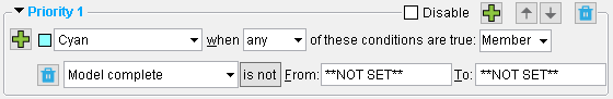
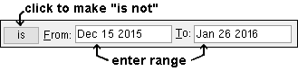
Model complete date: ' is / is not ' from ' a date ' to ' a second date '. ' ***Not Set*** ' is also a valid entry -- see entering dates .
|
| This example results in all model complete members in your current Modeling view being color coded cyan . To enter ** NOT SET **, type 0 then press Tab . See example 2. |
Example: For priority 1 in the active status display file , you enter ' is ' and a particular date range to " Detail complete date ." You select ' Member ' as the display item, then assign ' Blue ' as the display item's color and choose ' any ' as the display logic function. When you press " OK ," any members in your current view whose details have been assigned a " Detail complete " date within the designated date range are displayed in blue.
Example 2: Same as above, except that you enter ' is not ' and enter '** NOT SET **' for both " From " and " To ." Those members in your current view that have a " Model complete date " other than '** NOT SET **' are displayed in the color you designated.
Member display: The same members are color coded regardless of whether ' Member ' or ' Ends ' or ' Left ' or ' Right ' is selected. Both ends of those members are color coded when ' Ends ' is selected.
Note: Process and Create Solids cannot change a member that has its " Model complete " date set, nor can it generate connections on members that frame to such a member. The member cannot be erased or deleted. All settings on the member's review window become read-only in a full-featured SDS2 program , just like they always are in an SDS2 review station . Users of a full-featured SDS2 program can change status settings that do not affect piecemarking or detailing. Also, users can change the member's detail.
Member review window: Model complete date
Status Report by XXX: Model complete
Hide Items: Model complete
Detail complete date: ' is / is not ' from ' a date ' to ' a second date '. ' ***Not Set*** ' is also a valid entry -- see entering dates .
Example: For priority 1 in the active status display file , you enter ' is ' and a particular date range to " Detail complete date ." You select ' Blue ' as the display color and choose ' any ' as the display logic function. When you press " OK ," any members in your current view whose details have been assigned a " Detail complete " date within the designated date range are displayed in blue.
Member display: The same members are color coded regardless of whether ' Member ' or ' Ends ' or ' Left ' or ' Right ' is selected. Both ends of those members are color coded when ' Ends ' is selected.
Note: Setting a detail complete date prevents a drawing from being automatically detailed in a full-featured SDS2 program , A detail complete date can be assigned to a group member as well as to a member.
Warning: In views that display a great number of members, setting a status display color for members with a detail complete date may cause Redraw to slow down.
Drawing Data: Detail complete
Status Update: Detail complete
Other ways to set: Open
Status Report by XXX: Detail complete
Hide Items: Detail complete
Member left end locked: Yes or No . The check box found on the [ Left end settings ] banner of a member's review window shows whether or not that member's left end has been locked/unlocked in a full-featured SDS2 program .
Member left end locked ( 
Member left end unlocked ( 
When ' Yes ' is selected, the condition is true for members that have their [ Left end settings ] locked (
When ' No ' is selected, the condition is true for members that have their [ Left end settings ] unlocked (
A column member's left end is its bottom end. The check box for locking the left end of a column is found on the column review window's [ Bottom end settings ] banner.
Member display: The same members are color coded regardless of whether ' Member ' or ' Ends ' or ' Left ' or ' Right ' is selected. Both ends of those members are color coded when ' Ends ' is selected.
Member right end locked: Yes or No . Same as " Member left end locked ," except that this applies to a member's right end.
Member piecemark frozen: Yes or No .
| Member piecemark frozen : |
|
|
| Member piecemark not frozen : |
|
|
When ' Yes ' is selected, the condition is true for members with frozen piecemaks. Members with frozen piecemarks have a number greater than 0 entered as the " Piecemark group " on their review window ( Beam or Column or Horizontal Brace or Vertical Brace or Joist or etc.).
When ' No ' is selected, the condition is true for members whose piecemarks are not frozen. Members whose piecemarks are not frozen have ' 0 ' assigned as their " Piecemark group " on their review window.
Member display: The same members are color coded regardless of whether ' Member ' or ' Ends ' or ' Left ' or ' Right ' is selected. Both ends of those members are color coded when ' Ends ' is selected.
Status Update: Piecemark status Member review windows:
Frozen piecemark , Piecemark group
Topic: frozen piecemarks
Member detail frozen: Yes or No . When a member detail is frozen, it is in a read-only state in a full-featured SDS2 program , similar to its read-only state in an SDS2 review station .
| Member detail frozen : |
|
|
| Not member detail frozen : |
|
|
When ' Yes ' is selected, the condition is true for members that have a " Detail frozen " date set on their Drawing Data window in the Drawing Editor.
When ' No ' is selected, the condition is true for members whose details have ' **NOT SET** " as their entry to " Detail frozen " on their Drawing Data window. The condition is also true for members that have no details.
Member display: The same members are color coded regardless of whether ' Member ' or ' Ends ' or ' Left ' or ' Right ' is selected. Both ends of those members are color coded when ' Ends ' is selected.
Drawing Data: Detail frozen
Status Update: Detail frozen date
Submitted for approval: ' is / is not ' from ' a date ' to ' a second date '. ' ***Not Set*** ' is also a valid entry -- see entering dates .
Example: For priority 1 in the active status display file , you enter ' is ' to " Submitted for approval ." You select ' Member ' as the display item, then assign ' Orange ' as the display item's color and choose ' any ' as the display logic function. When you press " OK ," any members in your current view that have a " Submitted for approval " date within the designated date range are displayed in orange.
Member display: The same members are color coded regardless of whether ' Member ' or ' Ends ' or ' Left ' or ' Right ' is selected. Both ends of those members are color coded when ' Ends ' is selected.
Note: A " Submitted for approval " date may be interpreted as the date when documents pertaining to particular members were sent for engineering approval, but ultimately the term is entirely user-definable.
Status Update: Submitted for approval
Member Status Review: Submitted for approval
Status Report by XXX: Submitted for approval
Received from approval: ' is / is not ' from ' a date ' to ' a second date '.
Example: For priority 1 in the active status display file , you enter ' is ' and a particular date range to " Received from approval ." You select ' Member ' as the display item, then assign ' Maroon ' as the display item's color and choose ' any ' as the display logic function. When you press " OK ," any members in your current view that have a " Received from approval " date that is within the designated date range are displayed in the color maroon.
Member display: The same members are color coded regardless of whether ' Member ' or ' Ends ' or ' Left ' or ' Right ' is selected. Both ends of those members are color coded when ' Ends ' is selected.
Note: A " Received from approval " date may be interpreted as being the date when documents pertaining to particular members were returned from the engineering office after having been reviewed, but ultimately the term is entirely user-definable.
Status Update: Received from approval
Member Status Review: Received from approval
Status Report by XXX: Received from approval
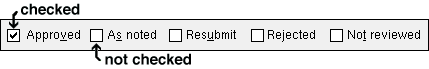
Approval status: ' Approved ' or ' Approved as noted ' or ' Resubmit ' or ' Rejected ' or ' Not reviewed '.
Status Update: Approval status
Member Status Review: Approval status
Status Report by XXX: Approval status
model > | status display | status select | status (index) | top
------ Fabrication status ------
Projected: ' is / is not ' from ' a date ' to ' a second date '. ' ***Not Set*** ' is also a valid entry -- see entering dates .
Example 1: For priority 1 in the active status display file , you enter ' is ' and a particular date range to " Projected ." You select ' Member ' as the display item, then assign a particular display color and choose ' any ' as the display logic function. When you press " OK ," any members in your current view that have a " Projected for fabrication " date that is within the date range you entered are displayed in the color you selected.
Example 2: Same as above, except that you enter 'is not'. Any members with a " Projected for fabrication " date that is not within the date range are displayed in the color you designated (including members to which no " Projected for fabrication " date has been assigned).
Member display: The same members are color coded regardless of whether ' Member ' or ' Ends ' or ' Left ' or ' Right ' is selected. Both ends of those members are color coded when ' Ends ' is selected.
Note: A " Projected for fabrication " date may be interpreted as signifying the date at which the member is scheduled to be fabricated, but ultimately the term is entirely user-definable.
Status Update: Projected for fabrication
Member Status Review: Projected fabrication complete
Status Report by XXX: Projected for fabrication
Approved: ' is / is not ' from ' a date ' to ' a second date '. See entering dates
Example: For priority 1 in the active status display file , you enter ' is ' and a particular date range to " Approved ." You select ' Member ' as the display item, then assign a particular display color and choose ' any ' as the display logic function. When you press " OK ," any members whose " Approval status " is ' Approved ' or ' Approved as noted ' and whose " Received from approval " date is within the range you entered are displayed in the color you selected.
Member display: The same members are color coded regardless of whether ' Member ' or ' Ends ' or ' Left ' or ' Right ' is selected. Both ends of those members are color coded when ' Ends ' is selected.
Released: ' is / is not ' from ' a date ' to ' a second date '. ' ***Not Set*** ' is also a valid entry -- see entering dates .
Example: For priority 1 in the active status display file , you enter ' is ' to " Released ." You select ' Member ' as the display item, then assign ' Blue ' as the display item's color and choose ' any ' as the display logic function. When you press the " OK " button, any members with a " Released for fabrication " date that is within the date range you entered are displayed in the color blue.
Member display: The same members are color coded regardless of whether ' Member ' or ' Ends ' or ' Left ' or ' Right ' is selected. Both ends of those members are color coded when ' Ends ' is selected.
Note: The " Released for fabrication " date is usually interpreted as signifying the date on which the member's detail was sent to the shop so that the member could be fabricated, but ultimately the term is entirely user-definable.
Status Update: Released for fabrication
Member Status Review: Released for fabrication
Status Report by XXX: Released for fabrication
Completed: ' is / is not ' from ' a date ' to ' a second date '. ' ***Not Set*** ' is also a valid entry -- see entering dates .
Example: For priority 1 in the active status display file , you enter ' is ' to " Completed ." You select ' Member ' as the display item, then assign ' Cyan ' as the display item's color and choose ' any ' as the display logic function. When you press " OK ," any members that have a " Fabrication completed " date that is within the date range you entered are displayed in the color cyan.
Member display: The same members are color coded regardless of whether ' Member ' or ' Ends ' or ' Left ' or ' Right ' is selected. Both ends of those members are color coded when ' Ends ' is selected.
Note: The " Fabrication complete " date is usually interpreted as signifying the date which the member was fabricated in the shop and is ready to ship, but ultimately the term is user-definable.
Status Update: Fabrication complete
Member Status Review: Fabrication completed
Status Report by XXX: Fabrication complete
Schedule met: Yes or No .
When ' Yes ' is selected, the condition is true for members whose " Fabrication complete " date is less than its " Projected for fabrication " date.
When ' No ' is selected, the condition is true for any member whose " Fabrication completed " date is greater than its fabrication " Projected for fabrication " date.
Member display: The same members are color coded regardless of whether ' Member ' or ' Ends ' or ' Left ' or ' Right ' is selected. Both ends of those members are color coded when ' Ends ' is selected.
Status Report by XXX: Fabrication completed on time
model > | status display | status select | status (index) | top
------ Shipping and erection status ------
Shipping projected: ' is / is not ' from ' a date ' to ' a second date '. ' ***Not Set*** ' is also a valid entry -- see entering dates .
Example 1: For priority 1 in the active status display file , you enter ' is ' and a particular date range " Shipping projected ." You select ' Member ' as the display item, then assign ' Orange ' as the display item's color and choose ' any ' as the display logic function. When you press the " OK " button, any members that have a " Projected to ship " date that is within the date range you entered are displayed in the color orange.
Example 2: Same as above, except that you enter ' is not '. Any members that have a " Projected to ship " date that is not within the date range are displayed in the color orange (including members to which no " Projected to ship " date has been assigned).
Member display: The same members are color coded regardless of whether ' Member ' or ' Ends ' or ' Left ' or ' Right ' is selected. Both ends of those members are color coded when ' Ends ' is selected.
Note: The " Projected to ship " date is usually interpreted as signifying the date which the member is scheduled to be shipped, but ultimately the term is user-definable.
Status Update: Projected to ship
Member Status Review: Projected shipped date
Status Report by XXX: Projected to ship
Shipping actual: ' is / is not ' from ' a date ' to ' a second date '. ' ***Not Set*** ' is also a valid entry -- see entering dates .
Example: For priority 1 in the active status display file , you enter ' is ' and a particular date range to " Shipping actual ." You select ' Member ' as the display item, then assign ' Magenta ' as the display item's color and choose ' any ' as the display logic function. When you press " OK ," any members that have an " Actual ship date " that is within the date range you entered are displayed in the color magenta.
Member display: The same members are color coded regardless of whether ' Member ' or ' Ends ' or ' Left ' or ' Right ' is selected. Both ends of those members are color coded when ' Ends ' is selected.
Note: The " Actual ship date " is usually interpreted as signifying the date which the member was transported to the construction site, but ultimately the term is user-definable.
Status Update: Actually shipped
Member Status Review: Actual ship date
Status Report by XXX: Actually shipped
Shipping schedule met: Yes or No .
When ' Yes ' is selected, the condition is true when a member's shipping schedule has been met. A member's shipping schedule is met when its " Shipping actual " date is less than its " Shipping projected " date.
When ' No ' is selected, the condition is true when a member's shipping schedule has not been met. A member whose shipping schedule has not been met is any member whose " Shipping actual " date is greater than its " Shipping projected " date.
Member display: The same members are color coded regardless of whether ' Member ' or ' Ends ' or ' Left ' or ' Right ' is selected. Both ends of those members are color coded when ' Ends ' is selected.
Status Report by XXX: Shipped on time
At job site: ' is / is not ' from ' a date ' to ' a second date '. ' ***Not Set*** ' is also a valid entry -- see entering dates .
Example: For priority 1 in the active status display file , you enter ' is ' and a particular date range to " At job site ." You select ' Member ' as the display item, then assign ' Orange ' as the display item's color and choose ' any ' as the display logic function. When you press " OK ," any members that have a " Received on job site " date that is within the date range you entered are displayed in the color orange.
Member display: The same members are color coded regardless of whether ' Member ' or ' Ends ' or ' Left ' or ' Right ' is selected. Both ends of those members are color coded when ' Ends ' is selected.
Note: The ' Received on job site " date is usually interpreted as signifying the date which the member was taken into inventory at the construction site, but ultimately the term is user-definable.
Status Update: Received on job site
Member Status Review: Received on job site
Status Report by XXX: Received at jobsite
Erected: ' is / is not ' from ' a date ' to ' a second date '. ' ***Not Set*** ' is also a valid entry -- see entering dates .
Example 1: For priority 1 in the active status display file , you enter ' is ' and a particular date range here, to " Erected ." You select ' Member ' as the display item, then assign a particular display color and choose ' any ' as the display logic function. When you press " OK ," any members that have an " Erected " date that is within the date range you entered are displayed in the color you selected.
Example 2: Same as above, except that you enter ' is not '. Any members that have an " Erected " date that is not within the designated date range are displayed in the color you selected (including members to which no " Erected " date has been assigned).
Member display: The same members are color coded regardless of whether ' Member ' or ' Ends ' or ' Left ' or ' Right ' is selected. Both ends of those members are color coded when ' Ends ' is selected.
Note: The " Erected " date is usually interpreted as signifying the date which the member was actually incorporated into the structure being built, but ultimately the term is user-definable.
Status Update: Erected
Member Status Review: Erected
Status Report by XXX: Erected
Member lift assignment: ' is / is not ' assigned to be lifted by a particular ' crane (placement) '. In the example below, TEREX is the crane and P2 is the placement .
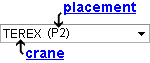
When you select a particular ' crane (placement) ', the condition reported in the " Legend " becomes, " Members assigned to be lifted by crane ' crane ' at placement ' (placement) '."
Example: The crane named TEREX has two placements, P1 and P2. Consequently, ' TEREX (P1) ' and ' TEREX (P2) ' are selectable options for this field. You select ' TEREX (P1) ' then press create a new condition and select ' TEREX (P2) '. You select ' Member ' as the display item, then assign a display color and ' any ' as the display logic to apply to the two condition statements, which in the " Legend " are as follows:
" Members assigned to be lifted by crane 'TEREX' at placement 'P1 '
" Members assigned to be lifted by crane 'TEREX' at placement 'P2'Since P1 and P2 are the only placements assigned to crane TEREX , when you press the " OK " button or the " Apply " button, all members that are to be lifted by the crane TEREX are displayed in the color you specified.
Member display: The same members are color coded regardless of whether ' Member ' or ' Ends ' or ' Left ' or ' Right ' is selected. Both ends of those members are color coded when ' Ends ' is selected.
To get a crane: A crane and crane placement can be added to in Modeling using tools that are available in the Site Planning program, which is a type of SDS2 review station .
Display Options: Cranes , Crane placements .
Member review window: Lift assignment
Assigned members liftable: Yes or No . Members may be assigned to be lifted at a particular crane placement using the Site Planning program. Each lift is either liftable or failed.
When ' Yes ' is selected, the condition is true for members that are liftable.
When ' No ' is selected, the condition is true for members that have failed or which have not yet had any lifts assigned.
Member display: The same members are color coded regardless of whether ' Member ' or ' Ends ' or ' Left ' or ' Right ' is selected. Both ends of those members are color coded when ' Ends ' is selected.
Assigned members critical: Yes or No . Members may be assigned to be lifted at a particular crane placement using the Site Planning program. A member that is liftable may have its lift marked as critical due to factors such as the crane's lifting capacity or the crane's reach.
When ' Yes ' is selected, the condition is true for members whose lift " Status " is marked as ' Success (Critical) '.
When ' No ' is selected, the condition is true for members other than those members whose lift " Status " is marked as ' Success (Critical) '.
Member display: The same members are color coded regardless of whether ' Member ' or ' Ends ' or ' Left ' or ' Right ' is selected. Both ends of those members are color coded when ' Ends ' is selected.
model > | status display | status select | status (index) | top
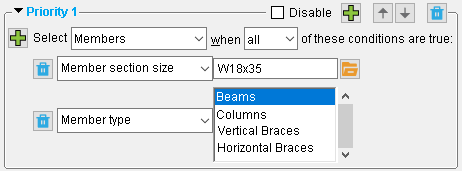
Member section size: ' any section size ' that is listed in the local shape file '. Text case does not matter (e.g., w14x90 is interpreted as being the same as W14x90).
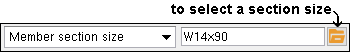
|
Or you can type in the section size. |
Example: For priority 1 in the active status display file , you select ' W14x90 ' along with ' Member ' as the display item, a display color and ' any ' as the display logic. The " Legend " will read: "[the selected color] when any of these conditions are true: Member Section Size is W14x90." When you press the " OK " button or the " Apply " button, any members in your current view that have the above-listed section size are displayed in the selected color.
Member display: The same members are color coded regardless of whether ' Member ' or ' Ends ' or ' Left ' or ' Right ' is selected. Both ends of those members are color coded when ' Ends ' is selected.
Also see: To set the display of submaterials (including member main material), see " Material section size ." The function keys F10-F12 and the * key on the keypad can be used to type in a section size.
Member type: ' Beam ' and/or ' Joist ' and/or ' Horizontal brace ' and/or ' Miscellaneous ' and/or ' Column ' and/or ' Stair ' and/or ' Vertical brace ' and/or ' Purlin ' and/or ' Anchor rod ' and/or ' Embed plate ' and/or ' Handrail ' and/or ' Anchor rod ' and/or ' Embed plate ' and/or ' Handrail ' and/or any other custom member type whose parametric script has been placed in the plugins folder ( ![]() ) that is used by your current version of this program. For example, if the caged ladder custom member plugin has been placed in that folder, ' Caged Ladder ' will be available as an option on the menu (
) that is used by your current version of this program. For example, if the caged ladder custom member plugin has been placed in that folder, ' Caged Ladder ' will be available as an option on the menu ( ![]() ) for this field.
) for this field.
|
|
| This example is for Status Select , not Status Display . It selects all W18x35 beams that are in your current view. |
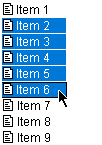
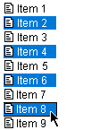
You can select multiple member types (items) as demonstrated below:
|
Click an item to select that item and deselect all other items. |
|
Drag or hold down the Shift key to select multiple items that are next to each other. |
|
Hold down the Ctrl key to select multiple items that are not next to each other. |
Example: You want to hide handrail members because they clutter your view. For priority 1 in the active status display file , you select ' Handrail ' as the " Custom member type " and set the display logic to ' Member ' and ' masked ' and ' any '. When you press " OK ," any handrail custom members that are in your current view are made invisible.
Member display: The same members are color coded regardless of whether ' Member ' or ' Ends ' or ' Left ' or ' Right ' is selected. Both ends of those members are color coded when ' Ends ' is selected.
Status Display: Members can be in a stick or solid form.
Status Select & Filter: ' Members ' or ' Member ends ' can be selected.
Selection filter: User and Site Options > Modeling > " Level of detail " must be sufficient.
Steel grade: ' any steel grade ' that is listed at Home > Project Settings > Job > Material Grades .
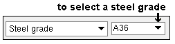
Example: All main materials in your current Job have a steel grade of A992. All connection materials use A36 as the steel grade. For priority 1 in the active status display file , you select ' A992 ' as the " Steel grade " and set the display logic to ' Member ' and ' Blue ' and ' any '. The " Legend " reads: Blue when any of these conditions are true: Steel grade is A992." When you press " OK ," all members in your current view are displayed in the color blue.
Member display: The same members are color coded regardless of whether ' Member ' or ' Ends ' or ' Left ' or ' Right ' is selected. Both ends of those members are color coded when ' Ends ' is selected.
When ' Yes ' is selected, the condition is true for any beam that has a " Camber " applied to it on its Beam Review window.
When ' No ' is selected, the condition is true for members that do not have camber.
Member display: The same members are color coded regardless of whether ' Member ' or ' Ends ' or ' Left ' or ' Right ' is selected. Both ends of those members are color coded when ' Ends ' is selected.
When ' Yes ' is selected, the condition is true for any member that has been set to be "
When ' No ' is selected, the condition is true for members that have not been set to be galvanized.
Member display: The same members are color coded regardless of whether ' Member ' or ' Ends ' or ' Left ' or ' Right ' is selected. Both ends of those members are color coded when ' Ends ' is selected.
Member review windows: Galvanized
Hide Items: Galvanized
Surface Finish: any surface finish ' that is listed at Home > Project Settings > Job > Surface Finishes
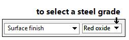
Example: All members in the current Job have a surface finish of Red oxide. Two members are set to Gray Oxide For priority 1 in the active status display file , you select ' Red oxide ' as the " Surface finish " and set the display logic to ' Member ' and ' Blue ' and ' any '. The " Legend " reads: " Blue when any of these conditions are true: Surface finish is Red oxide." When you press " OK ," all members except for two are displayed in the color blue.
Member display: The same members are color coded regardless of whether ' Member ' or ' Ends ' or ' Left ' or ' Right ' is selected. Both ends of those members are color coded when ' Ends ' is selected.
Report Writer:MemberMaterial.Material.SurfaceFinish
Setup:Surface Finish Settings
When ' Yes ' is selected, the condition is true for beams with " Composite design " checked (
When ' No ' is selected, the condition is true for all members that are not composite.
Member display: The same members are color coded regardless of whether ' Member ' or ' Ends ' or ' Left ' or ' Right ' is selected. Both ends of those members are color coded when ' Ends ' is selected.
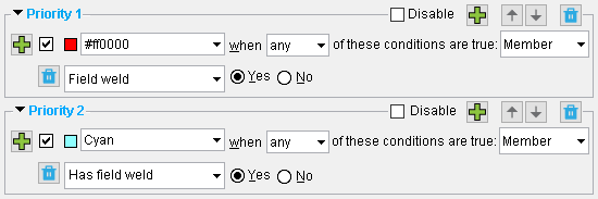
|
| The Priority 2 condition color codes (cyan) those members that have at least one field weld. The Priority 1 condition color codes red the field welds themselves. Switching the order of these priorities would give different results. If the priority 2 condition were to be made priority 1, the field weld would not be red -- it would be cyan along with the member. |
When ' Yes ' is selected, the condition is true when a member has a 3D weld that is set to "
When ' No ' is selected, the condition is true when a member does not have any of its 3D welds set to "
Member display: The same members are color coded regardless of whether ' Member ' or ' Ends ' or ' Left ' or ' Right ' is selected. Both ends of those members are color coded when ' Ends ' is selected.
Has input setback: Yes or No .
| Review window option that affects " Has input setback " | |
| Beam | " Input material setback " |
| Column | " Material setback " |
When ' Yes ' is selected, the condition may be true when a user has entered a value to " Input material setback " on a Beam Review window, or when a user has made an entry to " Material setback " on a Column Review window. When ' Member ' is selected as the item to be color coded , members with input setbacks (either end) are color coded. When ' Ends ' is selected, only those ends that have an input setback are color coded. When ' Left ' is selected, the left ends of members that have a left-end input setback are color coded. For a column, the bottom end is its left end.
When ' No ' is selected, the condition is true (regardless of whether ' Member ' or ' Ends ' or ' Left ' or ' Right ' is selected) when no entry has been made to " Input material setback " (both ends, Beam Review window) and an "
Member display: The same members are color coded regardless of whether ' Member ' or ' Ends ' or ' Left ' or ' Right ' is selected. Both ends of those members are color coded when ' Ends ' is selected.
Category: ' any category ' listed on the Category Settings window.
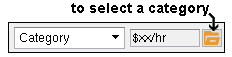
Example: The user of a full-featured SDS2 program enters $xx/hr and a number of other categories to the Category Settings window in Fabricator Options . That user then applies these categories to individual members in the model using " Member category " on the Status Review window. On the Status Display window (this window), you select ' $xx/hr ' using the "file cabinet" browse button (
Member display: The same members are color coded regardless of whether ' Member ' or ' Ends ' or ' Left ' or ' Right ' is selected. Both ends of those members are color coded when ' Ends ' is selected.
Status Update: Category
Member Status Review: Member category
Status Report by XXX: Category
Hide Items: Category
Member route 'Mult Cutting #' or ' ... ': ' any routing definition ' entered to the user routing configuration 1 . Configuration 1 definitions are entered to line 1 of the " Mult. Cutting # " column on the member bill of material.
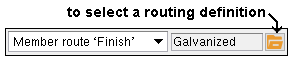
Example: In Fabricator Options , the user of a full-featured SDS2 program enters "Galvanized" and a number of other categories to the User Routing Category window for routing configuration 1. You apply these categories to individual members using " Member route . . . " on the Status Review window. On the Status Display window (this window), you select " Galvanized " using the "file cabinet" browse button (
Member display: The same members are color coded regardless of whether ' Member ' or ' Ends ' or ' Left ' or ' Right ' is selected. Both ends of those members are color coded when ' Ends ' is selected.
Member Status Review: Mult Cutting # or . ..
Status Report by XXX: Mult Cutting # or . .
Member route 'Labor Code' or ' ... ': Same as above , except that here you enter a definition from user routing configuration 2 . Configuration 2 definitions are entered to line 1 of the " Labor Code " column on the member bill of material.
Member route 'Job Cost Code' or ' ... ': Same as above , except that here you enter a definition from user routing configuration 3 . Configuration 3 definitions are entered to line 1 of the " Job Cost Code " column on the member bill of material.
Member route 'Remarks' or ' ... ': Same as above , except that here you enter a definition from user routing configuration 4 . Configuration 4 definitions are entered to line 1 of the " Remarks " column on the member bill of material.
Member custom property: This status option lets you select a particular custom property and write an expression to color code, isolate, mask or make translucent those members which have been assigned a particular value or range of values for that custom property. Before using this option, you should have assigned properties to members by pressing the " Properties " button on a member review window (for example, " Properties " on the Column Review window).
| Example : |
|
|
| -- finds members whose "BackCheckedBy" entry is 'dld' |
1 . Select a custom property. All custom properties for members are listed on this list box (
). Example: "BackCheckedBy" is the custom property selected for the expression in the above example. If you find that no properties are listed, then custom property schema have not yet been defined in Setup .
2 . Select the operator you want to use to evaluate values that have been entered for the selected custom property. Example: "=" is the operator selected in the above example.
= equal to |= does not equal < less than <= less than or equal to > greater than >= greater than or equal to 3 . Enter (or select) the value you want to evaluate. Example: "dld" is the value entered in the above example. Tip: Be aware that specific types of custom property fields allow specific types of entries -- see Note 1.
4 . Set the status display logic , etc.
Note 1: Entries to a custom property can be a ' String ' (allows any characters) or ' Number ' (allows decimals, whole numbers or fractions) or ' Boolean ' (
Note 2: Even strings (aaa < bbb) can be evaluated numerically. And so can dates (**NOT SET** < Feb 5 2007 < Feb 8 2007).
Member notes: Yes or No . Notes may be added to members by pressing " Properties " button on a member review window (for example, " Properties " on the Column Review window).
When ' Yes ' is selected, the condition is true for members for which "
When ' No ' is selected, the condition is true for members for which "
Member display: The same members are color coded regardless of whether ' Member ' or ' Ends ' or ' Left ' or ' Right ' is selected. Both ends of those members are color coded when ' Ends ' is selected.
Member description: Any string of characters. Text case does not matter.
| Example : |
|
|
| Typing misc or Misc would get you the exact same results. |
This condition is true for members whose " Member description " is composed of the same letters as the string that is entered here.
Member display: The same members are color coded regardless of whether ' Member ' or ' Ends ' or ' Left ' or ' Right ' is selected. Both ends of those members are color coded when ' Ends ' is selected.
Member Status Review: Member description
Drawing Data: Drawing description
HSS long side orientation: Vertical or Horizontal . This applies to vertical braces and horizontal braces whose " Section size " is an HSS rectangular or tube section.
![]()
When ' Vertical ' is selected, the condition is true for vertical braces whose " Long side " is set to ' Vertical ' and horizontal braces whose " Long side " is ' Vertical ."
When ' Horizontal ' is selected, the condition is true for vertical braces whose " Long side " is set to ' Horizontal ' and horizontal braces whose " Long side " is ' Horizontal '.
Member display: The same members are color coded regardless of whether ' Member ' or ' Ends ' or ' Left ' or ' Right ' is selected. Both ends of those members are color coded when ' Ends ' is selected.
Vertical Brace Review: Long side
Horizontal Brace Review: Long side
' Yes ' sets a condition that is true for beams, braces and joists that have "
' No ' sets a condition that is true for beams, braces and joists that have "
Member display: The same members are color coded regardless of whether ' Member ' or ' Ends ' or ' Left ' or ' Right ' is selected. Both ends of those members are color coded when ' Ends ' is selected.
Status Display: Members can be in a stick or solid form.
Status Select & Filter: ' Members ' or ' Member ends ' can be selected.
By status display selection filtering: User and Site Options > Modeling > " Level of detail " must be sufficient.
Beam Review: Swap member ends
Horizontal Brace Review: Swap member ends
Vertical Brace Review: Swap member ends
Joist Review: Swap member ends
Auto minus dimension: Yes or No .
' Yes ' sets a condition that may be true for members that have "
Automatic minus dimension " selected on their edit windows. When ' Member ' is selected as the item to be color coded , members with an auto minus dimension (either end) are color coded. When ' Ends ' is selected, only those member ends that have an auto minus dimension are color coded. When ' Left ' is selected, the left ends of members that have a left-end auto minus dimension are color coded.
' No ' sets a condition that is true for members that do not have an auto minus dimension on either end. If ' Ends ' or ' Lef t' or ' Right ' is selected, the condition may also be true for other circumstances.
Status Display: Members can be in a stick or solid form.
Status Select & Filter: ' Members ' or ' Member ends ' or ' Connection component s ' can be selected.
Selection filter: User and Site Options > Modeling > " Level of detail " must be sufficient.
Beam Review: Automatic minus dimension (left or right end)
Column Review: Minus dimension (left or right end)
Horizontal Brace Review: Automatic minus dimension (left or right end)
Vertical Brace Review: Automatic minus dimension (left or right end)
Auto material setback: Yes or No .
' Yes ' sets a condition that may be true for beams and columns that have auto material setbacks (either end) . The ' Yes ' condition may also true for braces and joists. When ' Member ' is selected as the item to be color coded , members with an auto material setback (either end) are color coded. When ' Ends ' is selected, only those member ends that have an auto material setback are color coded. When ' Left ' is selected, the left ends of members that have a left-end auto material setback are color coded.
' No ' sets a condition that is true for members that do not have an auto material setback on either end. If ' Ends ' or ' Lef t' or ' Right ' is selected, the condition may also be true for other circumstances.
Status Display: Members can be in a stick or solid form.
Status Select & Filter: ' Members ' or ' Member ends ' or ' Connection component s ' can be selected.
Selection filter: User and Site Options > Modeling > " Level of detail " must be sufficient.
Beam Review: Automatic material setback (left or right end)
Column Review: Material setback (left or right end)
Left end minus dimension: A positive or negative distance (in the primary dimension " Units " or other units ). Normally a minus dimension is positive, but users are permitted to enter a negative minus dimension in order to extend the member.
|
| = | equal to | != | does not equal | |
| < | less than | <= | less than or equal to | |
| > | greater than | >= | greater than or equal to |
Unit Conversion: If "
Left end display: When this condition is true, ' Ends ' or ' Left ' along with a color selection color codes a member's left end only. ' Member ' color codes the entire member.
Status Display: Members can be in a stick or solid form.
Status Select & Filter: ' Members ' or ' Member ends ' or ' Connection component s ' can be selected.
Selection filter: User and Site Options > Modeling > " Level of detail " must be sufficient.
Beam Review: Input minus dimension or Automatic minus dimension
Column Review: Minus dimension
Horizontal Brace Review: Input minus dimension or Automatic minus dimension
Vertical Brace Review: Input minus dimension or Automatic minus dimension
Right end minus dimension: Same as " Left end minus dimension ," except that this applies to a member's right end .
Left end field clearance: A distance (in the primary dimension " Units " or other units ).
|
| = | equal to | != | does not equal | |
| < | less than | <= | less than or equal to | |
| > | greater than | >= | greater than or equal to |
Unit Conversion: If "
Left end display: When this condition is true, ' Ends ' or ' Left ' along with a color selection color codes a member's left end only. ' Member ' color codes the entire member.
Status Display: Members can be in a stick or solid form.
Status Select & Filter: Can select ' Members ' or ' Member ends ' or ' Connection component s '.
Selection filter: User and Site Options > Modeling > " Level of detail " must be sufficient.
Beam Review: Field clearance (left end)
Horizontal Brace Review: Field clearance (left end)
Vertical Brace Review: Field clearance (left end)
Right end field clearance: Same as " Left end field clearance ," except that this applies to a member's right end .
Left end material setback: A distance (in the primary dimension " Units " or other units ).
|
| = | equal to | != | does not equal | |
| < | less than | <= | less than or equal to | |
| > | greater than | >= | greater than or equal to |
Unit Conversion: If "
Left end display: When this condition is true, ' Ends ' or ' Left ' along with a color selection color codes a member's left end only. ' Member ' color codes the entire member.
Status Display: Members can be in a stick or solid form.
Status Select & Filter: Can select ' Members ' or ' Member ends ' or ' Connection component s '.
Selection filter: User and Site Options > Modeling > " Level of detail " must be sufficient.
Beam Review: Input material setback or Automatic material setback (left end)
Column Review: Material setback (left end)
Right end material setback: Same as " Left end material setback ," except that this applies to a member's right end .
Left end connection setback: A distance (in the primary dimension " Units " or other units ).
|
| = | equal to | != | does not equal | |
| < | less than | <= | less than or equal to | |
| > | greater than | >= | greater than or equal to |
Unit Conversion: If "
Left end display: When this condition is true, ' Ends ' or ' Left ' along with a color selection color codes a member's left end only. ' Member ' color codes the entire member.
Status Display: Members can be in a stick or solid form.
Status Select & Filter: Can select ' Members ' or ' Member ends ' or ' Connection component s '.
Selection filter: User and Site Options > Modeling > " Level of detail " must be sufficient.
Beam Review: Connection setback
Right end connection setback: Same as " Left end connection setback ," except that this applies to a member's right end .
Left end shear load: A load (in kips for ' Imperial ', kilonewtons for ' Metric ').
|
| = | equal to | != | does not equal | |
| < | less than | <= | less than or equal to | |
| > | greater than | >= | greater than or equal to |
Left end display: When this condition is true, ' Ends ' or ' Left ' along with a color selection color codes a member's left end only. ' Member ' color codes the entire member.
Status Display: Members can be in a stick or solid form.
Status Select & Filter: ' Members ' or ' Member ends ' or ' Connection component s ' can be selected.
Selection filter: User and Site Options > Modeling > " Level of detail " must be sufficient.
Beam Review: Shear load
Right end shear load: Same as " Left end shear load ," except that this applies to a member's right end .
Left end story shear: A load (in kips for ' Imperial ', kilonewtons for ' Metric ').
|
| = | equal to | != | does not equal | |
| < | less than | <= | less than or equal to | |
| > | greater than | >= | greater than or equal to |
Left end display: When this condition is true, a color and either ' Ends ' or ' Left ' color codes a member's left end. ' Member ' color codes the entire member.
Status Display: Members can be in a stick or solid form.
Status Select & Filter: Can select ' Members ' or ' Member ends ' or ' Connection component s '.
Selection filter: User and Site Options > Modeling > " Level of detail " must be sufficient.
Beam Review: Story shear
Right end story shear: Same as " Left end story shear ," except that this applies to a member's right end .
Left end moment load: A moment load (in kip-in or kip-ft for ' Imperial ', kilonewton-meters for ' Metric '). Note that moment loads can be positive or negative. On a beam, the sign of the left end moment defaults to positive and that of the right end defaults to negative.
|
| = | equal to | != | does not equal | |
| < | less than | <= | less than or equal to | |
| > | greater than | >= | greater than or equal to |
Note: A beam must have a left-end moment connection (see " Moment type ") before this condition can discover a moment load on the left end of that beam. Moment loads on the end of a member are not applicable when the member does not have a moment connection.
Left end display: When this condition is true, a color and either ' Ends ' or ' Left ' color codes a member's left end. ' Member ' color codes the entire member.
Status Display: Members can be in a stick or solid form.
Status Select & Filter: ' Members ' or ' Member ends ' or ' Connection component s ' can be selected.
Selection filter: User and Site Options > Modeling > " Level of detail " must be sufficient.
Beam Review: Moment load
Column Review: Moment
Right end moment load: Same as " Left end moment load ," except that this applies to a member's right end .
Left end tension load: A load (in kips for ' Imperial ', kilonewtons for ' Metric ').
|
| = | equal to | != | does not equal | |
| < | less than | <= | less than or equal to | |
| > | greater than | >= | greater than or equal to |
Left end display: When this condition is true, a color and either ' Ends ' or ' Left ' color codes a member's left end. ' Member ' color codes the entire member.
Status Display: Members can be in a stick or solid form.
Status Select & Filter: Can select ' Members ' or ' Member ends ' or ' Connection component s '.
Selection filter: User and Site Options > Modeling > " Level of detail " must be sufficient.
Beam Review: Tension load
Column Review: Splice uplift
Horizontal Brace Review: Tension load
Vertical Brace Review: Tension load
Right end tension load: Same as " Left end tension load ," except that this applies to a member's right end .
Left end compression load: A load (in kips for ' Imperial ', kilonewtons for ' Metric ').
|
| = | equal to | != | does not equal | |
| < | less than | <= | less than or equal to | |
| > | greater than | >= | greater than or equal to |
Left end display: When this condition is true, a color and either ' Ends ' or ' Left ' color codes a member's left end. ' Member ' color codes the entire member.
Status Display: Members can be in a stick or solid form.
Status Select & Filter: Can select ' Members ' or ' Member ends ' or ' Connection component s '.
Selection filter: User and Site Options > Modeling > " Level of detail " must be sufficient.
Beam Review: Compression load
Column Review: Load
Horizontal Brace Review: Compression load
Vertical Brace Review: Compression load
Right end compression load: Same as " Left end compression load ," except that this applies to a member's right end .
Left end moment type: Non moment or Welded moment or Bolted moment . Beams can have their " Moment type " set to ' Welded moment ' or ' Bolted moment '.
|
Example: Columns and braces and joists are, by default, considered to be ' Non moment ," and you can't add moment connections to them. If you want to find beams with non moment connections, you can set two conditions under the priority and make sure that ' all ' those two conditions are true. Those two conditions should be "Left end moment type = Non moment" and " Member type = Beam."
Left end display: When this condition is true, a color and either ' Ends ' or ' Left ' color codes a member's left end. ' Member ' color codes the entire member.
Status Display: Members can be in a stick or solid form.
Status Select & Filter: Can select ' Members ' or ' Member ends ' or ' Connection component s '.
Selection filter: User and Site Options > Modeling > " Level of detail " must be sufficient.
Beam Review: Moment type
Right end moment type: Same as " Left end moment type ," except that this applies to a member's right end .
Rolling operation: No roll or Camber annotation or Weak axis or Strong axis or Camber or Camber (both) . A " Rolling operation " can be applied to beams. A " Rolling operation " can also be applied to miscellaneous members that are rolled sections or bars.
|
Example: Columns and braces and joists and stairs are, by default, considered to be ' No roll ," and you can't add rolling operations to them. If you want to find beams with rolling operations, you can set two conditions under the priority and make sure that ' all ' those two conditions are true. Those two conditions should be "Left end moment type = Non moment" and " Member type = Beam."
Member display: The same members are color coded regardless of whether ' Member ' or ' Ends ' or ' Left ' or ' Right ' is selected. Both ends of those members are color coded when ' Ends ' is selected.
Status Display: Color codes members in a stick or solid form.
Status Select & Filter: Can select ' Members ' or ' Member ends ' or ' Connection component s '.
Selection filter: User and Site Options > Modeling > " Level of detail " must be sufficient.
Beam Review: Rolling operation
Mid-ordinate: A positive or negative distance (in the primary dimension " Units " or other units ).
|
| = | equal to | != | does not equal | |
| < | less than | <= | less than or equal to | |
| > | greater than | >= | greater than or equal to |
Unit Conversion: If "
Member display: The same members are color coded regardless of whether ' Member ' or ' Ends ' or ' Left ' or ' Right ' is selected. Both ends of those members are color coded when ' Ends ' is selected.
Status Display: Color codes members in a stick or solid form.
Status Select & Filter: Can select ' Members ' or ' Member ends ' or ' Connection component s '.
Selection filter: User and Site Options > Modeling > " Level of detail " must be sufficient.
Beam Review: Mid-ordinate
Included angle: A positive or negative angle (degrees).
|
| = | equal to | != | does not equal | |
| < | less than | <= | less than or equal to | |
| > | greater than | >= | greater than or equal to |
Member display: The same members are color coded regardless of whether ' Member ' or ' Ends ' or ' Left ' or ' Right ' is selected. Both ends of those members are color coded when ' Ends ' is selected.
Status Display: Color codes members in a stick or solid form.
Status Select & Filter: Can select ' Members ' or ' Member ends ' or ' Connection component s '.
Selection filter: User and Site Options > Modeling > " Level of detail " must be sufficient.
Beam Review: Included angle
Rolling radius: A positive or negative distance (in the primary dimension " Units " or other units ).
|
| = | equal to | != | does not equal | |
| < | less than | <= | less than or equal to | |
| > | greater than | >= | greater than or equal to |
Unit Conversion: If "
Member display: The same members are color coded regardless of whether ' Member ' or ' Ends ' or ' Left ' or ' Right ' is selected. Both ends of those members are color coded when ' Ends ' is selected.
Status Display: Color codes members in a stick or solid form.
Status Select & Filter: Can select ' Members ' or ' Member ends ' or ' Connection component s '.
Selection filter: User and Site Options > Modeling > " Level of detail " must be sufficient.
Beam Review: Rolling radius
Spiral offset: A positive or negative distance (in the primary dimension " Units " or other units ).
|
| = | equal to | != | does not equal | |
| < | less than | <= | less than or equal to | |
| > | greater than | >= | greater than or equal to |
Unit Conversion: If "
Member display: The same members are color coded regardless of whether ' Member ' or ' Ends ' or ' Left ' or ' Right ' is selected. Both ends of those members are color coded when ' Ends ' is selected.
Status Display: Color codes members in a stick or solid form.
Status Select & Filter: Can select ' Members ' or ' Member ends ' or ' Connection component s '.
Selection filter: User and Site Options > Modeling > " Level of detail " must be sufficient.
Beam Review: Spiral offset
Member number: You can select one or more members. All members in the model are available on the list that you can select from. Each listing represents a single member.
| Example : | ||||||
|
||||||
| More than one member can be selected as shown below. |
|
|
Click an item to select that item and deselect all other items. |
|
Drag or hold down the Shift key to select multiple items that are next to each other. |
|
Hold down the Ctrl key to select multiple items that are not next to each other. |
Member display: The same members are color coded regardless of whether ' Member ' or ' Ends ' or ' Left ' or ' Right ' is selected. Both ends of those members are color coded when ' Ends ' is selected.
Status Display: Color codes members in a stick or solid form.
Status Select & Filter: Can select ' Members ' or ' Member ends ' or ' Connection component s '.
Selection filter: User and Site Options > Modeling > " Level of detail " must be sufficient.
Topic: Member number
Topic: Member piecemarks
Member piecemark: You can select one or more members . All members in the model are available on the list that you can select from. Since multiple members may be batched under a single member piecemark, each listing may represent one or more members.
| Example : | ||||||
|
||||||
| More than one piecemark can be selected as shown below. |
|
Click an item to select that item and deselect all other items. |
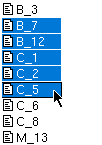
|
Drag or hold down the Shift key to select multiple items that are next to each other. |
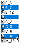
|
Hold down the Ctrl key to select multiple items that are not next to each other. |
Member display: The same members are color coded regardless of whether ' Member ' or ' Ends ' or ' Left ' or ' Right ' is selected. Both ends of those members are color coded when ' Ends ' is selected.
Status Display: Color codes members in a stick or solid form.
Status Select & Filter: Can select ' Members ' or ' Member ends ' or ' Connection component s '.
Selection filter: User and Site Options > Modeling > " Level of detail " must be sufficient.
Topic: Member piecemarks
' Yes ' sets a condition that is true for members that have been grouped together in a full-featured SDS2 program .
' No ' sets a condition that is true for members that have not been grouped.
Member display: The same members (all members in each member group) are color coded regardless of whether ' Member ' or ' Ends ' or ' Left ' or ' Right ' is selected. Both ends of those members are color coded when ' Ends ' is selected.
Status Display: Color codes members in a stick or solid form.
Status Select & Filter: Can select ' Members ' or ' Member ends ' or ' Connection component s '.
Selection filter: User and Site Options > Modeling > " Level of detail " must be sufficient.
model > | status display | status select | status (index) | top
------ Group member status ------
Group piecemark: You can select one or more group members. All group members in the model are available on the list that you can select from. Since multiple group members may be batched under a single group member piecemark, each listing may represent one or more group members.
| Example : | ||||||
|
||||||
| More than one piecemark can be selected as shown below. |
|
|
Click an item to select that item and deselect all other items. |
|
Drag or hold down the Shift key to select multiple items that are next to each other. |
|
Hold down the Ctrl key to select multiple items that are not next to each other. |
Member display: The same members (all members in each member group) are color coded regardless of whether ' Member ' or ' Ends ' or ' Left ' or ' Right ' is selected. Both ends of those members are color coded when ' Ends ' is selected.
Status Display: Members can be in a stick or solid form.
Status Select & Filter: Can select ' Members ' or ' Member ends ' or ' Connection component s '.
Selection filter: User and Site Options > Modeling > " Level of detail " must be sufficient.
Group Member Review: System piecemark or User piecemark .
Group description: Any string of characters. Text case does not matter.
| Example : | ||||
|
||||
| Typing truss or Truss would get you the exact same result. |
Member display: The same members (all members in each member group) are color coded regardless of whether ' Member ' or ' Ends ' or ' Left ' or ' Right ' is selected. Both ends of those members are color coded when ' Ends ' is selected.
Status Display: Members can be in a stick or solid form.
Status Select & Filter: Can select ' Members ' or ' Member ends ' or ' Connection component s '.
Selection filter: User and Site Options > Modeling > " Level of detail " must be sufficient.
Group Member Review: Description
When ' Yes ' is selected, the condition is true for group members that have been set to "
When ' No ' is selected, the condition is true for group members that are not galvanized as well as for beams, columns and braces.
Example: If you want to color code group members that have not been group galvanized, you can set two conditions under the priority and make sure that ' all ' those two conditions are true. Those two conditions should be "Group galvanized = No" and " Grouped member = Yes."
Member display: The same members (all members in each member group) are color coded regardless of whether ' Member ' or ' Ends ' or ' Left ' or ' Right ' is selected. Both ends of those members are color coded when ' Ends ' is selected.
Status Display: Members can be in a stick or solid form.
Status Select & Filter: Can select ' Members ' or ' Member ends ' or ' Connection component s '.
Selection filter: User and Site Options > Modeling > " Level of detail " must be sufficient.
Group Member Review: Galvanized
Group custom property: A group member property applies to the group member itself, not to any of the submembers that make up that group member. This status option lets you select a particular custom property and write an expression to color code, isolate, mask or make translucent which custom group members have been assigned a particular value or range of values for that custom property. Before using this option, you should have assigned properties to group members by pressing the " Properties " button on the Group Member Review window.
| Example : | |||||||||
|
|||||||||
| -- is true for members whose "CheckedBy" entry is 'John' |
1 . Select a custom property. All custom properties for group members are listed on this list box (
2 . Select the operator you want to use to evaluate values that have been entered for the selected custom property. Example: "=" is the operator selected in the above example.
= equal to |= does not equal < less than <= less than or equal to > greater than >= greater than or equal to 3 . Enter (or select) the value you want to evaluate. Example: "John" is the value entered in the above example. Tip : Be aware that specific types of custom property fields allow specific types of entries -- see Note 1.
4 . Set the status display logic , etc.
Note 1: Entries to a custom property can be a ' String ' (allows any characters) or ' Number ' (allows decimals, whole numbers or fractions) or ' Boolean ' (
Note 2: Even strings (aaa < bbb) can be evaluated numerically. And so can dates (**NOT SET** < Feb 5 2007 < Feb 8 2007).
Status Display: Members can be in a stick or solid form.
Status Select & Filter: Can select ' Members ' or ' Member ends ' or ' Connection component s '.
Selection filter: User and Site Options > Modeling > " Level of detail " must be sufficient.
Group Member Review: The " Properties " button at the bottom of the window.
model > | status display | status select | status (index) | top
Material section size: ' any section size ' in the local shape file . Text case does not matter (e.g., w14x90 is interpreted as being the same as W14x90).
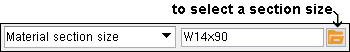
|
Or you can type in the section size. |
Example: For priority 1 in the active status display file , you select ' W16x50 ' as the " Material section size " and set the display logic to ' Red ' and ' any '. The " Legend ' will read: "Red when any of these conditions are true: Section size is W16x50." When you press the " OK " button or the " Apply " button, any W16x50 sections in your current view that are in a solids form are displayed in the color red.
Material display: For materials to be color coded or masked or made translucent, members must be displayed in a solid form. This is also required for the selection of ' Materials ' or ' Connection components ' using Status Select or the ' By Status Display ' selection filter. To color code all materials, ' Member ' needs to be selected as the display item. To color code only member main materials, you can select ' Ends ' or ' Left ' or ' Right '.
Status Select: ' Members ' or ' Materials ' or ' Connection components ' can be selected based on the choice made to " Material type ." This is also true for the ' By Status Display ' selection filter.
Also see: " Member section size " can color code the entire member (in stick or solids form) based on its main material section size. The function keys F10-F12 and the * key on the keypad can be used to type in a section size.
Material steel grade: ' any steel grade ' that is listed at Home > Project Settings > Job > Material Grades . This condition can affect the display of submaterials and member main materials.
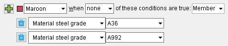
|
| Note that ' None ' is used in this example. The condition and display logic color codes ( maroon ) those materials in your current view that do not have A36 or A992 as their steel grade. |
Material display: For materials to be color coded or masked or made translucent, members must be displayed in a solid form. This is also required for the selection of ' Materials ' or ' Connection components ' using Status Select or the ' By Status Display ' selection filter. To color code all materials, ' Member ' needs to be selected as the display item. To color code only member main materials, you can select ' Ends ' or ' Left ' or ' Right '.
Status Select: ' Members ' or ' Materials ' or ' Connection components ' can be selected based on the choice made to " Material steel grade ." This is also true for the ' By Status Display ' selection filter.
Selection filter: User and Site Options > Modeling > " Level of detail " must be sufficient if you want to be able to select materials using the ' By Status Display ' selection filter.
Material plate thickness: This applies to all plate materials, including rectangular plate , bent plate , round plate , rolled plate , flat plate layout and bent plate layout materials.
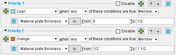
|
| 1/2 inch plates are included in both ranges in this example. Since priority 1 takes precedence, 1/2 inch plates will be displayed in the color cyan (not as orange). |
Imperial or metric: You can enter thicknesses in the primary dimension " Units " or other units .
Gage thicknesses may be designated with an entry such as 11ga .
Ranges: You can enter a range (e.g. 0 to 1/2) or the same thickness twice (e.g. 1/2 to 1/2).
Material display: For materials to be color coded or masked or made translucent or made translucent, members must be displayed in a solid form. This is also required for the selection of ' Materials ' or ' Connection components ' using Status Select or the ' By Status Display ' selection filter. To ensure that all plate materials are color coded, ' Member ' needs to be selected as the display item. To color code only the main materials of welded plate members, you can select ' Ends ' or ' Left ' or ' Right '.
Rectangular Plate Material: Material thickness
Bent Plate Material: Material thickness
Round Plate Material: Material thickness
Rolled Plate Material: Material thickness
Flat Plate Layout: Material thickness
Bent Plate Layout: Material thickness
Material fitted, mitred or coped: Yes or No .
When ' Yes ' is selected, the condition is true for materials on which Fit operations have been performed in a full-featured SDS2 program in order to cope, notch or, in other ways, cut materials. The condition is also true when certain " Drain/Vent Hole " patterns have been added in the Base / Cap Plate Schedule .
When ' No ' is selected, the condition is true for materials on which a Fit operation has not been performed.
Material display: This status condition affects the display of submaterials. Members must be in a solid form before any submaterials of those members can be displayed per the display logic that is set for this status condition. ' Member ' should be selected as the display item.
Material bent: Yes or No .
When ' Yes ' is selected, the condition us true for materials that the user of a full-featured SDS2 program has bent using Bend on Line or Bend on Radius Point operations.
When ' No ' is selected, the condition us true for materials that have not been bent using Bend on Line or Bend on Radius Point .
Material display: This status condition affects the display of submaterials. Members must be in a solid form before any submaterials of those members can be displayed per the display logic that is set for this status condition. ' Member ' should be selected as the display item.
Material stretched: Yes or No .
When ' Yes ' is selected, the condition is true when the user of a full-featured SDS2 program has altered a material using a Stretch Material operation.
When ' No ' is selected, the condition is true for materials that have not been stretched.
Material display: This status condition affects the display of submaterials. Members must be in a solid form before any submaterials of those members can be displayed per the display logic that is set for this status condition. ' Member ' should be selected as the display item.
Material surface finish: 'is/is not ' ' None ' or ' Sandblasted ' or ' Red oxide ' or ' Yellow zinc ' or ' Gray oxide ' or ' Blued steel ' or ' Galvanized ' or ' Duplex Coating ' or ' Undefined 1 ' or ' Undefined 2 ' or ' Undefined 3 ' or ' Red oxide 2 '.
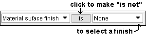
Example: For priority 1 in the active status display file , you select ' is not ' along with ' Red oxide ' for " Material Surface finish " and set the display logic to ' Member ' and ' Cyan ' and ' any '. The " Legend ' will read: "Cyan when any of these conditions are true: Material surface finish is not Red oxide." When you press the " OK " button or the " Apply " button, any materials in your current view that have a surface finish other than red oxide are shown in the color cyan.
Material display: For materials to be color coded or masked or made translucent, members must be displayed in a solid form. This is also required for the selection of ' Materials ' or ' Connection components ' using Status Select or the ' By Status Display ' selection filter. To color code all materials, ' Member ' needs to be selected as the display item. To color code only member main materials, you can select ' Ends ' or ' Left ' or ' Right '.
Status Select: ' Members ' or ' Materials ' or ' Connection components ' can be selected based on the choice made to " Material surface finish ." This is also true for the ' By Status Display ' selection filter.
Selection filter: User and Site Options > Modeling > " Level of detail " must be sufficient if you want to be able to select materials using the ' By Status Display ' selection filter.
Channel toe direction: In or Out .
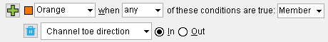
|
| The condition and display logic shown here can display channels whose " Toe direction " is set to ' In ' in the color orange . |
Material display: This status condition affects the display of submaterials. Members must be in a solid form before any submaterials of those members can be displayed per the display logic set for this status condition. To color code all materials, ' Member ' needs to be selected as the display item. To color code only member main materials, you can select ' Ends ' or ' Left ' or ' Right '.
Rolled Section Material: Toe direction
Angle long leg orientation: Vertical or Horizontal .
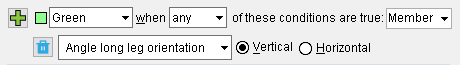
|
| The condition and display logic shown here can display channels whose " Long leg " is set to ' Vertical ' in the color green . |
Material display: This status condition affects the display of submaterials. Members must be in a solid form before any submaterials of those members can be displayed per the display logic set for this status condition. To color code all materials, ' Member ' needs to be selected as the display item. To color code only member main materials, you can select ' Ends ' or ' Left ' or ' Right '.
Rolled Section Material: Long leg
Material route 'Mult Cutting #' or ' ... ': ' any routing definition ' entered to the User Routing Category window for user routing configuration 1 '. Configuration 1 routing definitions are compiled in the " Mult. Cutting # " column on the member bill of material.
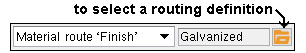
Example: You select " Galvanized " using the "file cabinet" browse button (
Material route 'Labor Code' or ' ... ': Same as above , except that here you enter a definition from user routing configuration 2 .
Material route 'Job Cost Code' or ' ... ': Same as above , except that here you enter a definition from user routing configuration 3 .
Material route 'Remarks' or ' ... ': Same as above , except that here you enter a definition from user routing configuration 4 .
Material custom property: This status option lets you select a particular custom property and write an expression to color code which materials have been assigned a particular value or range of values for that custom property. Before using this option : Material schema must have been defined in Setup , and you also should have assigned custom properties to materials by pressing the " Properties " button on the General Information window. Members must be in a solid form before any submaterials of those members can be displayed based on a status condition that is set using this option.
| Example : |
|
|
| -- finds materials whose "date_checked" date is **NOT CHECKED** or earlier than Feb 6 2007. |
1 . Select a custom property. All custom properties for materials are listed in the list box (
2 . Select the operator you want to use to evaluate values that have been entered for the selected custom property. Example: "<" is the operator selected in the above example.
= equal to |= does not equal < less than <= less than or equal to > greater than >= greater than or equal to 3 . Enter (or select) the value you want to evaluate. Example: "Feb 6 2007" is the value entered in the above example. Tip : Be aware that specific types of custom property fields allow specific types of entries -- see Note 1.
4 . Set the status display logic , etc.
Note 1: Entries to a custom property can be a ' String ' (allows any characters) or ' Number ' (allows decimals, whole numbers or fractions) or ' Boolean ' (
Note 2: Even strings (aaa < bbb) can be evaluated numerically. And so can dates (**NOT SET** < Feb 5 2007 < Feb 8 2007).
Material notes: Yes or No . Notes may be added to materials by pressing " Properties " button on the General Information window.
When ' Yes ' is selected, the condition is true for materials that have "
When ' No ' is selected, the condition is true for materials that do not have "
Material display: This status condition affects the display of materials. Members must be in a solid form before any submaterials of those members can be displayed per the display logic set for this status condition. ' Member ' should be selected as the display item.
Material description: Any string of characters. Text case does not matter (e.g."L4x3 1/2X5/16" is interpreted as being the same as "L4x3 1/2x5/16").
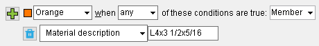
|
| The condition and display logic shown here can color code ( orange ) all L4x3 1/2x5/16 angles. The angles may be of various lengths. |
Descriptions: For materials in Shapes Properties , the standard description is the " Section Size " entered in the local shape file . For materials not in Shapes Properties , full-featured SDS2 programs apply the appropriate description prefix from the Member and Material Piecemarking window in setup.
Material display: For materials to be color coded or masked or made translucent, members must be displayed in a solid form. This is also required for the selection of ' Materials ' or ' Connection components ' using Status Select or the ' By Status Display ' selection filter. ' Member ' should be selected as the display item.
General Information: Description .
Material usage description: Any string of characters. Text case does not matter (e.g."rafter_web_0" is interpreted as being the same as "RAFTER_WEB_0").
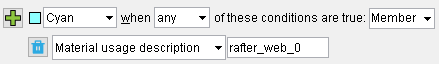
|
| The condition and display logic shown color codes ( cyan ) any materials that have the usage description 'rafter_web_0'. |
Material usage descriptions: For members such as beams, columns, etc., SDS2 programs do not automatically apply material usage descriptions. Users of a full-featured SDS2 program need to manually apply them to a material using " Material usage description " on the material's General Information window. However, parametrically added material such as, for example, a material that is a part of a custom member , may automatically include a material description that might be used for detailing-with-templates purposes.
Material display: For materials to be color coded or masked or made translucent, members must be displayed in a solid form. This is also required for the selection of ' Materials ' or ' Connection components ' using Status Select or the ' By Status Display ' selection filter. ' Member ' should be selected as the display item.
Status Select: ' Members ' or ' Materials ' or ' Connection components ' can be selected based on the choice made to " Material usage description ." This is also true for the ' By Status Display ' selection filter.
Selection filter: User and Site Options > Modeling > " Level of detail " must be sufficient if you want to be able to select materials using the ' By Status Display ' selection filter.
Job Setup: Material Usage Descriptions
General Information: > Material usage description
Material detail complete date: ' is / is not ' from ' a date ' to ' a second date '. ' ***Not Set*** ' is also a valid entry -- see entering dates .
Example: For priority 1 in the active status display file , you enter ' is ' and a particular date range here, to " Material detail complete date ." You set the display logic to ' Member ' and ' Blue ' and ' any '. When you press " OK ," any members in your current view whose details have been assigned a " Detail complete " date that is within the designated date range are displayed in blue.
Relevance: A detail complete date prevents a drawing from undergoing automatic detailing in a full-featured SDS2 program .
Warning: In views that display a great number of materials, setting a status display color for materials with a detail complete date may cause Redraw to slow down.
Drawing Data: Detail complete
Hide Items: Detail complete
Main material: Yes or No . This applies only to materials that are parts of member types such as beams, columns and braces. It does not apply to miscellaneous members and stairs.
' Yes ' sets a condition that is true for materials that are designated as User modified main member material or System created main member material on their General Information windows.
' No ' sets a condition that is true for connection materials.
Material display: For materials to be color coded or masked or made translucent, members must be displayed in a solid form. This is also required for the selection of ' Materials ' using Status Select or the ' By Status Display ' selection filter. The same member main materials are color coded regardless of whether ' Member ' or ' Ends ' or ' Left ' or ' Right ' is selected. Both ends of those member main materials are color coded when ' Ends ' is selected.
Status Select: ' Members ' or ' Materials ' can be selected based on the choice made to " Main material ." When " Main material " is ' No ," ' Connection components ' can be selected. This is also true for the ' By Status Display ' selection filter.
Selection filter: User and Site Options > Modeling > " Level of detail " must be sufficient if you want to be able to select materials using the ' By Status Display ' selection filter.
Hide Items: Main material
General Information: User modified main member material
General Information: System created main member material
Material type: You can select one or more material types . Any of the material types in SDS2 can be selected from the list. Each listed material type may represent multiple pieces in the model since many different pieces can be the same material type.
| Example : | ||||||
|
||||||
| More than one material type can be selected as shown below. |
|
|
Click an item to select that item and deselect all other items. |
|
Drag or hold down the Shift key to select multiple items that are next to each other. |
|
Hold down the Ctrl key to select multiple items that are not next to each other. |
Status Display: For materials to be color coded or masked or made translucent, members must be displayed in a solid form. This is also required for the selection of ' Materials ' or ' Connection components ' using Status Select or the ' By Status Display ' selection filter.
Material display: For materials to be color coded or masked or made translucent, members must be displayed in a solid form. This is also required for the selection of ' Materials ' or ' Connection components ' using Status Select or the ' By Status Display ' selection filter. To color code all materials, ' Member ' needs to be selected as the display item. To color code only member main materials, you can select ' Ends ' or ' Left ' or ' Right '.
Selection filter: User and Site Options > Modeling > " Level of detail " must be sufficient if you want to be able to select materials using the ' By Status Display ' selection filter.
Topic: Material types in SDS2
model > | status display | status select | status (index) | top
------ Bolt status ------
Bolt type: A325N or A325SC or A325X or etc. Bolt types that can be selected in the list box ( ![]() ) for this field come from the Bolt Specifications .
) for this field come from the Bolt Specifications .
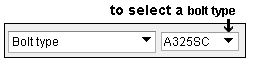
Example: For priority 1 in the active status display file , you select ' A325SC ' to " Bolt type " and set the display logic to ' Member ' and ' Cyan ' and ' any '. The " Legend " will read: "Cyan when any of these conditions are true: Bolt type is A325SC." When you press " OK ," any A325SC bolts that are visible in your current view are displayed in the color cyan.
Bolt display: For bolts to be color coded or masked or made translucent, the display of " Bolts " needs to be turned on in Display Options , and members must be displayed in a solid form. These are also requirements for the selection of ' Bolts ' using Status Select or the ' By Status Display ' selection filter. For Status Display , ' Member ' must be selected as the display item.
Status Select: ' Members ' or ' Bolts ' can be selected based on the choice made to " Bolt type description ." This is also true for the ' By Status Display ' selection filter.
Selection Filter: User and Site Options > Modeling > " Level of detail " must be sufficient if you want to be able to select bolts using the ' By Status Display ' selection filter.
Bolt material: A307 or A325 or A490 or F1852 or F2280 are the bolt materials that are supported by default. Any other bolt materials that can be selected on the list box ( ![]() ) for this field were added to the Bolt Specifications by users.
) for this field were added to the Bolt Specifications by users.
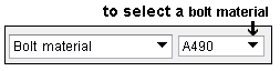
Example: For priority 1 in the active status display file , you select ' A490 ' and set the display logic to ' Member ' and ' Blue ' and ' any '. The complete condition statement will read: "Blue when any of these conditions are true: Bolt material is A490." When you press the " OK " button or the " Apply " button, any A490 bolts that are visible in your current view are displayed in the color blue.
Why these five bolt materials? Connection design recognizes A325/F1852 and A490/F2280 as materials for high strength connections. A307 material is recognized as material for "soft bolts" and used for " Erection bolts ."
Bolt display: For bolts to be color coded or masked or made translucent, the display of " Bolts " needs to be turned on in Display Options , and members must be displayed in a solid form. These are also requirements for the selection of ' Bolts ' using Status Select or the ' By Status Display ' selection filter. For Status Display , ' Member ' must be selected as the display item.
Selection Filter: ' Members ' or ' Bolts ' can be selected based on the choice made to " Bolt material ." This is also true for the ' By Status Display ' selection filter.
By Status Display: User and Site Options > Modeling > " Level of detail " must be sufficient if you want to be able to select bolts using the ' By Status Display ' selection filter.
Bolt Review: Bolt type
Bolt diameter: ' is / is not ' from ' a bolt diameter ' to ' a second bolt diameter '. The same bolt diameter twice (e.g. 5/8 to 5/8) designates a single bolt diameter.
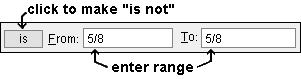
Making an entry: You can enter any diameter in the primary dimension " Units " or other units . If "
Example: For priority 1 in the active status display file , you enter 'is' and a particular diameter range to " Bolt diameter " and set the display logic to ' Member ' and ' Green ' and ' any '. When you press " OK ," any bolts that are visible in your current view and that are within the diameter range you entered are displayed in the color green.
Bolt display: For bolts to be color coded or masked or made translucent, the display of " Bolts " needs to be turned on in Display Options , and members must be displayed in a solid form. These are also requirements for the selection of ' Bolts ' using Status Select or the ' By Status Display ' selection filter. For Status Display , ' Member ' must be selected as the display item.
Status Select: ' Members ' or ' Bolts ' can be selected based on the choice made to " Bolt diameter ." This is also true for the ' By Status Display ' selection filter.
Selection Filter: User and Site Options > Modeling > " Level of detail " must be sufficient if you want to be able to select bolts using the ' By Status Display ' selection filter.
Bolt Review: Diameter
Bolt length: ' is / is not ' from ' a bolt length ' to ' a second bolt length '. The same bolt length twice (e.g. 2 to 2) designates a single bolt length.
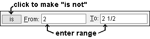
Unit Conversion: If "
Example: For priority 1 in the active status display file , you enter 'is' and a particular range to " Bolt length " and set the display logic to ' Member ' and ' Aqua ' and ' any '. When you press " OK ," any bolts that are visible in your current view and within the length range that you entered are displayed in the color aqua.
Bolt display: For bolts to be color coded or masked or made translucent, the display of " Bolts " needs to be turned on in Display Options , and members must be displayed in a solid form. These are also requirements for the selection of ' Bolts ' using Status Select or the ' By Status Display ' selection filter. For Status Display , ' Member ' must be selected as the display item.
Status Select: ' Members ' or ' Bolts ' can be selected based on the choice made to " Bolt length ." This is also true for the ' By Status Display ' selection filter.
Selection Filter: User and Site Options > Modeling > " Level of detail " must be sufficient if you want to be able to select bolts using the ' By Status Display ' selection filter.
Bolt Review: Bolt length
Bolt grip: ' is / is not ' from ' a bolt grip to ' a second bolt grip '. The same bolt grip twice (e.g. 5/8 to 5/8) designates a single bolt grip.
Unit Conversion: If "
Example: For priority 1 in the active status display file , you enter 'is not' and a particular range to " Bolt grip " and set the display logic to ' Member ' and ' Lavender ' and ' any '. When you press " OK ," any bolts that are visible in your current view and that are not within the length range you entered are displayed in the color lavender.
Bolt display: For bolts to be color coded or masked or made translucent, the display of " Bolts " needs to be turned on in Display Options , and members must be displayed in a solid form. These are also requirements for the selection of ' Bolts ' using Status Select or the ' By Status Display ' selection filter. For Status Display , ' Member ' must be selected as the display item.
Status Select: ' Members ' or ' Bolts ' can be selected based on the choice made to " Bolt grip ." This is also true for the ' By Status Display ' selection filter.
Selection Filter: User and Site Options > Modeling > " Level of detail " User and Site Options > Modeling > must be sufficient if you want to be able to select bolts using the ' By Status Display ' selection filter.
Bolt Review: Bolt grip
' Yes ' sets a condition that is true for bolts that have " Class " set to ' Field bolts ' on their Bolt Review window. In other words, ' Yes ' finds field bolts.
' No ' sets a condition that is true for bolts that have " Class " set to ' Shop bolts ' on their Bolt Review window. In other words, ' Yes ' finds shop bolts.
Bolt display: For bolts to be color coded or masked or made translucent, the display of " Bolts " needs to be turned on in Display Options , and members must be displayed in a solid form. These are also requirements for the selection of ' Bolts ' using Status Select or the ' By Status Display ' selection filter. For Status Display , ' Member ' must be selected as the display item.
Status Select: ' Members ' or ' Bolts ' can be selected based on the choice made to " Field bolt ." This is also true for the ' By Status Display ' selection filter.
Selection Filter: User and Site Options > Modeling > " Level of detail " must be sufficient if you want to be able to select bolts using the ' By Status Display ' selection filter.
Bolt Review: Class
' Yes ' sets a condition that is true for bolts that have "
' No ' sets a condition that is true for bolts that have "
Bolt display: For bolts to be color coded or masked or made translucent, the display of " Bolts " needs to be turned on in Display Options , and members must be displayed in a solid form. These are also requirements for the selection of ' Bolts ' using Status Select or the ' By Status Display ' selection filter. For Status Display , ' Member ' must be selected as the display item.
Status Select: ' Members ' or ' Bolts ' can be selected based on the choice made to " Tension control ." This is also true for the ' By Status Display ' selection filter.
Selection Filter: User and Site Options > Modeling > " Level of detail " must be sufficient if you want to be able to select bolts using the ' By Status Display ' selection filter.
Bolt Review: Tension control
Bolt finish: ' is / is not ' plated with a particular ' finish '.
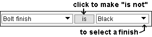
Bolt display: For bolts to be color coded or masked or made translucent, the display of " Bolts " needs to be turned on in Display Options , and members must be displayed in a solid form. These are also requirements for the selection of ' Bolts ' using Status Select or the ' By Status Display ' selection filter. For Status Display , ' Member ' must be selected as the display item.
Status Select: ' Members ' or ' Bolts ' can be selected based on the choice made to " Bolt finish ." This is also true for the ' By Status Display ' selection filter.
Selection Filter: User and Site Options > Modeling > " Level of detail " must be sufficient if you want to be able to select bolts using the ' By Status Display ' selection filter.
Bolt Review: Finish
Bolt custom property: You cannot edit bolt custom properties in an SDS2 review station . However, if users of, for example, SDS2 Detailing have applied custom properties to bolts in your current Job , then you can use this option to color-code by category the bolt custom properties that those users have applied.
Primary nut type: None (no primary nut) or Heavy hex or Heavy square or Jam . If a bolt has two nuts, the primary nut is the one closest to the material that is being fastened. The secondary nut is the one closest to the end of the bolt.
|
Note: ' None ' as the " Primary nut type " normally indicates a bolt without a nut.
Bolt display: For bolts to be color coded or masked or made translucent, the display of " Bolts " needs to be turned on in Display Options , and members must be displayed in a solid form. These are also requirements for the selection of ' Bolts ' using Status Select or the ' By Status Display ' selection filter. For Status Display , ' Member ' must be selected as the display item.
Status Select: ' Members ' or ' Bolts ' can be selected based on the choice made to " Primary nut type ." This is also true for the ' By Status Display ' selection filter.
Selection Filter: User and Site Options > Modeling > " Level of detail " must be sufficient if you want to be able to select bolts using the ' By Status Display ' selection filter.
Bolt Review: Primary nut type
Primary nut grade: A563 or A563-C or A563-DH or A194 or etc. .
|
Bolt display: For bolts to be color coded or masked or made translucent, the display of " Bolts " needs to be turned on in Display Options , and members must be displayed in a solid form. These are also requirements for the selection of ' Bolts ' using Status Select or the ' By Status Display ' selection filter. For Status Display , ' Member ' must be selected as the display item.
Status Select: ' Members ' or ' Bolts ' can be selected based on the choice made to " Primary nut grade ." This is also true for the ' By Status Display ' selection filter.
Selection Filter: User and Site Options > Modeling > " Level of detail " must be sufficient if you want to be able to select bolts using the ' By Status Display ' selection filter.
Bolt Review: Primary nut grade
Secondary nut type: None (no secondary nut) or Heavy hex or Heavy square or Jam . If a bolt has two nuts, the primary nut is the one closest to the material that is being fastened. The secondary nut is the one closest to the end of the bolt.
|
Note: ' None ' is the default " Secondary nut type " since SDS2 programs do not normally design bolts with two nuts.
Bolt display: For bolts to be color coded or masked or made translucent, the display of " Bolts " needs to be turned on in Display Options , and members must be displayed in a solid form. These are also requirements for the selection of ' Bolts ' using Status Select or the ' By Status Display ' selection filter. For Status Display , ' Member ' must be selected as the display item.
Status Select: ' Members ' or ' Bolts ' can be selected based on the choice made to " Secondary nut type ." This is also true for the ' By Status Display ' selection filter.
Selection Filter: User and Site Options > Modeling > " Level of detail " must be sufficient if you want to be able to select bolts using the ' By Status Display ' selection filter.
Bolt Review: Secondary nut type
Secondary nut grade: A563 or A563-C or A563-DH or A194 or etc. .
|
Note: Even if a bolt does not have a secondary nut, a secondary nut grade will be assigned on that bolt's review window.
Bolt display: For bolts to be color coded or masked or made translucent, the display of " Bolts " needs to be turned on in Display Options , and members must be displayed in a solid form. These are also requirements for the selection of ' Bolts ' using Status Select or the ' By Status Display ' selection filter. For Status Display , ' Member ' must be selected as the display item.
Status Select: ' Members ' or ' Bolts ' can be selected based on the choice made to " Secondary nut grade ." This is also true for the ' By Status Display ' selection filter.
Selection Filter: User and Site Options > Modeling > " Level of detail " must be sufficient if you want to be able to select bolts using the ' By Status Display ' selection filter.
Bolt Review: Secondary nut grade
Primary washer under nut: None (no primary washer) or Hardened or Square plate or Round plate or Flat or Bevel or Direct tension indicator or Hillside or Double thick hardened or Heavy plate .
|
Bolt display: For bolts to be color coded or masked or made translucent, the display of " Bolts " needs to be turned on in Display Options , and members must be displayed in a solid form. These are also requirements for the selection of ' Bolts ' using Status Select or the ' By Status Display ' selection filter. For Status Display , ' Member ' must be selected as the display item.
Status Select: ' Members ' or ' Bolts ' can be selected based on the choice made to " Primary washer under nut ." This is also true for the ' By Status Display ' selection filter.
Selection Filter: User and Site Options > Modeling > " Level of detail " must be sufficient if you want to be able to select bolts using the ' By Status Display ' selection filter.
Bolt Review: Type (of primary washer under nut)
Secondary washer under nut: None (no secondary washer) or Hardened or Square plate or Round plate or Flat or Bevel or Direct tension indicator or Hillside or Double thick hardened or Heavy plate .
|
Bolt display: For bolts to be color coded or masked or made translucent, the display of " Bolts " needs to be turned on in Display Options , and members must be displayed in a solid form. These are also requirements for the selection of ' Bolts ' using Status Select or the ' By Status Display ' selection filter. For Status Display , ' Member ' must be selected as the display item.
Status Select: ' Members ' or ' Bolts ' can be selected based on the choice made to " Secondary washer under nut ." This is also true for the ' By Status Display ' selection filter.
Selection Filter: User and Site Options > Modeling > " Level of detail " must be sufficient if you want to be able to select bolts using the ' By Status Display ' selection filter.
Bolt Review: Type (of primary washer under nut)
Tertiary washer under nut: None (no tertiary washer) or Hardened or Square plate or Round plate or Flat or Bevel or Direct tension indicator or Hillside or Double thick hardened or Heavy plate .
|
Bolt display: For bolts to be color coded or masked or made translucent, the display of " Bolts " needs to be turned on in Display Options , and members must be displayed in a solid form. These are also requirements for the selection of ' Bolts ' using Status Select or the ' By Status Display ' selection filter. For Status Display , ' Member ' must be selected as the display item.
Status Select: ' Members ' or ' Bolts ' can be selected based on the choice made to " Tertiary washer under nut ." This is also true for the ' By Status Display ' selection filter.
Selection filter: User and Site Options > Modeling > " Level of detail " must be sufficient if you want to be able to select bolts using the ' By Status Display ' selection filter.
Bolt Review: Type (of primary washer under nut)
model > | status display | status select | status (index) | top
------ Hole status ------
Hole diameter: ' is / is not ' from ' a hole diameter ' to ' a second hole diameter '. The same hole diameter twice (e.g. 1/2 to 1/2) designates a single hole diameter.
|
|
Interpretation: This condition is true for holes whose " Hole diameter " is within the range that is entered here.
Unit Conversion: If "
Example: For priority 1 in the active status display file , you enter 'is' and a particular diameter range to " Hole diameter " and set the display logic to ' Fuchsia ' and ' any '. When you press " OK ," any holes that are visible in your current view and are within the diameter range that you entered are displayed in the color fuchsia.
Hole Edit: For holes to be color coded or masked or made translucent, the display of " Holes " needs to be turned on in Display Options , and members must be displayed in a solid form. These are also requirements for the selection of ' Holes ' using Status Select or the ' By Status Display ' selection filter. For Status Display , ' Member ' must be selected as the display item.
Status Select: ' Members ' or ' Holes ' can be selected based on the choice made to " Hole diameter ." This is also true for the ' By Status Display ' selection filter.
Selection filter: User and Site Options > Modeling > " Level of detail " must be sufficient if you want to be able to select holes using the ' By Status Display ' selection filter.
Hole Review: Hole diameter
Hole type: Standard round or Short slot or Oversized round or Long slot or Cope hole or Erection pin hole or Anchor bolt hole or Plug weld hole or Grout or User slot #1 or User slot #2 or Vent/Drain .
|
Interpretation: This condition is true for holes whose " Hole type " matches the selection that is made here.
Hole Edit: For holes to be color coded or masked or made translucent, the display of " Holes " needs to be turned on in Display Options , and members must be displayed in a solid form. These are also requirements for the selection of ' Holes ' using Status Select or the ' By Status Display ' selection filter. For Status Display , ' Member ' must be selected as the display item.
Status Select: ' Members ' or ' Holes ' can be selected based on the choice made to " Hole type ." This is also true for the ' By Status Display ' selection filter.
Selection filter: User and Site Options > Modeling > " Level of detail " must be sufficient if you want to be able to select holes using the ' By Status Display ' selection filter.
Hole Review: Hole type
Slot rotation: ' is / is not ' from ' a positive or negative number ' to ' another such number '. Validation for " Slot rotation " on the Hole Review window prevents rotations that are outside of a range from 90 to -90 degrees. This means, at least theoretically, that you should never see a slot in your model with a rotation that is less than -90 or greater than 90.
Example: Round holes, by default, have a " Slot rotation " of 0. This means, for example, if you want to find short slots with a slot rotation of zero, you should enter two conditions under the priority and make sure that ' all ' those two conditions are true. Those two conditions should be "Slot rotation = 0" and " Hole type = Short slot."
Hole Edit: For holes to be color coded or masked or made translucent, the display of " Holes " needs to be turned on in Display Options , and members must be displayed in a solid form. These are also requirements for the selection of ' Holes ' using Status Select or the ' By Status Display ' selection filter. For Status Display , ' Member ' must be selected as the display item.
Status Select: ' Members ' or ' Holes ' can be selected based on the choice made to " Slot rotation ." This is also true for the ' By Status Display ' selection filter.
Selection filter: User and Site Options > Modeling > " Level of detail " must be sufficient if you want to be able to select holes using the ' By Status Display ' selection filter.
Hole Review: Slot rotation
Slot length: ' is / is not ' from ' a slot length ' to ' a second slot length '. The same slot length twice (e.g. 1 to 1) designates a single slot length.
Interpretation: This condition is true for holes with a " Slot length " that is within the range that is entered here.
Unit Conversion: If "
Hole Edit: For holes to be color coded or masked or made translucent, the display of " Holes " needs to be turned on in Display Options , and members must be displayed in a solid form. These are also requirements for the selection of ' Holes ' using Status Select or the ' By Status Display ' selection filter. For Status Display , ' Member ' must be selected as the display item.
Status Select: ' Members ' or ' Holes ' can be selected based on the choice made to " Slot length ." This is also true for the ' By Status Display ' selection filter.
Selection filter: User and Site Options > Modeling > " Level of detail " must be sufficient if you want to be able to select holes using the ' By Status Display ' selection filter.
Hole Review: Slot length
Plug type: No plug or Zinc plug or Plug weld or Aluminum or Epoxy .
|
Example: Most of these apply only when the " Hole type " is ' Vent/Drain '. However, ' No plug ' is, by default, assigned to holes of all types. This means, for example, if you want to find vent/drain holes with no plugs, you should enter two conditions under the priority and make sure that ' all ' those two conditions are true. Those two conditions should be "Plug type = No plug" and " Hole type = Vent/Drain."
Hole Edit: For holes to be color coded or masked or made translucent, the display of " Holes " needs to be turned on in Display Options , and members must be displayed in a solid form. These are also requirements for the selection of ' Holes ' using Status Select or the ' By Status Display ' selection filter. For Status Display , ' Member ' must be selected as the display item.
Status Select: ' Members ' or ' Holes ' can be selected based on the choice made to " Plug type ." This is also true for the ' By Status Display ' selection filter.
Selection filter: User and Site Options > Modeling > " Level of detail " must be sufficient if you want to be able to select holes using the ' By Status Display ' selection filter.
Hole Review: Plug type
' Yes ' sets a condition that is true for holes that have "
' No ' sets a condition that is true for holes that have "
Hole Edit: For holes to be color coded or masked or made translucent, the display of " Holes " needs to be turned on in Display Options , and members must be displayed in a solid form. These are also requirements for the selection of ' Holes ' using Status Select or the ' By Status Display ' selection filter. For Status Display , ' Member ' must be selected as the display item.
Status Select: ' Members ' or ' Holes ' can be selected based on the choice made to " Matchable ." This is also true for the ' By Status Display ' selection filter.
Selection filter: User and Site Options > Modeling > " Level of detail " must be sufficient if you want to be able to select holes using the ' By Status Display ' selection filter.
Hole Review: Matchable
Preferred bolt type: A325N or A325SC or etc. The types of bolts that can be selected come from the Bolt Specifications .
|
Interpretation: This condition is true for holes whose " Preferred bolt type " matches the choice made here.
Hole Edit: For holes to be color coded or masked or made translucent, the display of " Holes " needs to be turned on in Display Options , and members must be displayed in a solid form. These are also requirements for the selection of ' Holes ' using Status Select or the ' By Status Display ' selection filter. For Status Display , ' Member ' must be selected as the display item.
Status Select: ' Members ' or ' Holes ' can be selected based on the choice made to " Preferred bolt type ." This is also true for the ' By Status Display ' selection filter.
Selection filter: User and Site Options > Modeling > " Level of detail " must be sufficient if you want to be able to select holes using the ' By Status Display ' selection filter.
Hole Review: Preferred bolt type
' Yes ' sets a condition that is true for holes that have " Hole depth " set to ' Thru ' on their Hole Review window. In other words, ' Yes ' finds thru holes.
' No ' sets a condition that is true for holes that have " Hole depth " set to ' Blind ' on their Hole Review window. In other words, ' No ' finds blind holes.
Hole Edit: For holes to be color coded or masked or made translucent, the display of " Holes " needs to be turned on in Display Options , and members must be displayed in a solid form. These are also requirements for the selection of ' Holes ' using Status Select or the ' By Status Display ' selection filter. For Status Display , ' Member ' must be selected as the display item.
Status Select: ' Members ' or ' Holes ' can be selected based on the choice made to " Thru hole ." This is also true for the ' By Status Display ' selection filter.
Selection filter: User and Site Options > Modeling > " Level of detail " must be sufficient if you want to be able to select holes using the ' By Status Display ' selection filter.
Hole Review: Hole depth
' Yes ' sets a condition that is true for holes that have " Hole depth " set to ' Blind ' on their Hole Review window. In other words, ' Yes ' finds blind holes.
' No ' sets a condition that is true for holes that have " Hole depth " set to ' Thru ' on their Hole Review window. In other words, ' No ' finds thru holes.
Hole Edit: For holes to be color coded or masked or made translucent, the display of " Holes " needs to be turned on in Display Options , and members must be displayed in a solid form. These are also requirements for the selection of ' Holes ' using Status Select or the ' By Status Display ' selection filter. For Status Display , ' Member ' must be selected as the display item.
Status Select: ' Members ' or ' Holes ' can be selected based on the choice made to " Blind hole ." This is also true for the ' By Status Display ' selection filter.
Selection filter: User and Site Options > Modeling > " Level of detail " must be sufficient if you want to be able to select holes using the ' By Status Display ' selection filter.
Hole Review: Hole depth
Blind hole depth: ' is / is not ' from ' a distance ' to ' a second distance '. The same distance twice (e.g. 9/16 to 9/16) designates a single blind hole depth.
Interpretation: This condition is true for holes with a " Countersink " diameter that is within the range that is entered here.
Unit Conversion: If "
Hole Edit: For holes to be color coded or masked or made translucent, the display of " Holes " needs to be turned on in Display Options , and members must be displayed in a solid form. These are also requirements for the selection of ' Holes ' using Status Select or the ' By Status Display ' selection filter. For Status Display , ' Member ' must be selected as the display item.
Status Select: ' Members ' or ' Holes ' can be selected based on the choice made to " Blind hole depth ." This is also true for the ' By Status Display ' selection filter.
Selection filter: User and Site Options > Modeling > " Level of detail " must be sufficient if you want to be able to select holes using the ' By Status Display ' selection filter.
Hole Review: Hole depth = Blind
' Yes ' sets a condition that is true for holes that have " Head type " set to ' Countersink ' on their Hole Review window. In other words, ' Yes ' finds countersink holes.
' No ' sets a condition that is true for holes that have " Hole head " set to ' No head (straight) ' or ' Counterbore ' on their Hole Review window. In other words, ' No ' finds holes that are not countersink holes.
Hole Edit: For holes to be color coded or masked or made translucent, the display of " Holes " needs to be turned on in Display Options , and members must be displayed in a solid form. These are also requirements for the selection of ' Holes ' using Status Select or the ' By Status Display ' selection filter. For Status Display , ' Member ' must be selected as the display item.
Status Select: ' Members ' or ' Holes ' can be selected based on the choice made to " Countersink ." This is also true for the ' By Status Display ' selection filter.
Selection filter: User and Site Options > Modeling > " Level of detail " must be sufficient if you want to be able to select holes using the ' By Status Display ' selection filter.
Hole Review: Head type = Countersink
Countersink diameter: ' is / is not ' from ' a diameter ' to ' a second diameter '. The same countersink diameter twice (e.g. 1 1/4 to 1 1/4) designates a single countersink diameter.
Interpretation: This condition is true for holes with a " Countersink " diameter that is within the range that is entered here.
Unit Conversion: If "
Hole Edit: For holes to be color coded or masked or made translucent, the display of " Holes " needs to be turned on in Display Options , and members must be displayed in a solid form. These are also requirements for the selection of ' Holes ' using Status Select or the ' By Status Display ' selection filter. For Status Display , ' Member ' must be selected as the display item.
Status Select: ' Members ' or ' Holes ' can be selected based on the choice made to " Countersunk diameter ." This is also true for the ' By Status Display ' selection filter.
Selection filter: User and Site Options > Modeling > " Level of detail " must be sufficient if you want to be able to select holes using the ' By Status Display ' selection filter.
Hole Review: Head type = Countersink
Countersink angle: ' is / is not ' from ' an angle (degrees) ' to ' a second angle (degrees) '. The same countersink number of degrees twice (e.g. 90 to 90) designates a single countersink angle.
Hole Edit: For holes to be color coded or masked or made translucent, the display of " Holes " needs to be turned on in Display Options , and members must be displayed in a solid form. These are also requirements for the selection of ' Holes ' using Status Select or the ' By Status Display ' selection filter. For Status Display , ' Member ' must be selected as the display item.
Status Select: ' Members ' or ' Holes ' can be selected based on the choice made to " Countersink angle ." This is also true for the ' By Status Display ' selection filter.
Selection filter: User and Site Options > Modeling > " Level of detail " must be sufficient if you want to be able to select holes using the ' By Status Display ' selection filter.
Hole Review: Head type = Countersink
' Yes ' sets a condition that is true for holes that have " Head type " set to ' Counterbore ' on their Hole Review window. In other words, ' Yes ' finds counterbore holes.
' No ' sets a condition that is true for holes that have " Hole head " set to ' No head (straight) ' or ' Countersink ' on their Hole Review window. In other words, ' No ' finds holes that are not counterbore holes.
Hole Edit: For holes to be color coded or masked or made translucent, the display of " Holes " needs to be turned on in Display Options , and members must be displayed in a solid form. These are also requirements for the selection of ' Holes ' using Status Select or the ' By Status Display ' selection filter. For Status Display , ' Member ' must be selected as the display item.
Status Select: ' Members ' or ' Holes ' can be selected based on the choice made to " Counterbore ." This is also true for the ' By Status Display ' selection filter.
Selection filter: User and Site Options > Modeling > " Level of detail " must be sufficient if you want to be able to select holes using the ' By Status Display ' selection filter.
Hole Review: Head type = Counterbore
Counterbore diameter: ' is / is not ' from ' a diameter ' to ' a second diameter '. The same counterbore diameter twice (e.g. 1 1/4 to 1 1/4) designates a single counterbore diameter.
Interpretation: This condition is true for holes with a " Counterbore " diameter that is within the range that is entered here.
Unit Conversion: If "
Hole Edit: For holes to be color coded or masked or made translucent, the display of " Holes " needs to be turned on in Display Options , and members must be displayed in a solid form. These are also requirements for the selection of ' Holes ' using Status Select or the ' By Status Display ' selection filter. For Status Display , ' Member ' must be selected as the display item.
Status Select: ' Members ' or ' Holes ' can be selected based on the choice made to " Counterbore diameter ." This is also true for the ' By Status Display ' selection filter.
Selection filter: User and Site Options > Modeling > " Level of detail " must be sufficient if you want to be able to select holes using the ' By Status Display ' selection filter.
Hole Review: Head type = Counterbore
Counterbore depth: ' is / is not ' from ' a depth ' to ' a second depth '. The same counterbore depth twice (e.g. 5/8 to 5/8) designates a single counterbore depth.
Interpretation: This condition is true for holes with a " Counterbore " depth that is within the range that is entered here.
Unit Conversion: If "
Hole Edit: For holes to be color coded or masked or made translucent, the display of " Holes " needs to be turned on in Display Options , and members must be displayed in a solid form. These are also requirements for the selection of ' Holes ' using Status Select or the ' By Status Display ' selection filter. For Status Display , ' Member ' must be selected as the display item.
Status Select: ' Members ' or ' Holes ' can be selected based on the choice made to " Counterbore depth ." This is also true for the ' By Status Display ' selection filter.
Selection filter: User and Site Options > Modeling > " Level of detail " must be sufficient if you want to be able to select holes using the ' By Status Display ' selection filter.
Hole Review: Head type = Counterbore
Threads: Yes or No . Be aware that only standard round holes can have threads.Other types of holes, such as slots, have no threads.
' Yes ' sets a condition that is true for holes that have "
' No ' sets a condition that is true for holes that have "
Hole Edit: For holes to be color coded or masked or made translucent, the display of " Holes " needs to be turned on in Display Options , and members must be displayed in a solid form. These are also requirements for the selection of ' Holes ' using Status Select or the ' By Status Display ' selection filter. For Status Display , ' Member ' must be selected as the display item.
Status Select: ' Members ' or ' Holes ' can be selected based on the choice made to " Threads ." This is also true for the ' By Status Display ' selection filter.
Selection filter: User and Site Options > Modeling > " Level of detail " must be sufficient if you want to be able to select holes using the ' By Status Display ' selection filter.
Hole Review: Threads
Thread major dia./size #: ' is / is not ' from ' a distance ' to ' a second distance '.
Interpretation: This condition is true for holes whose " Major Dia / Size # " is within the range that is entered here.
Unit Conversion: If "
Hole Edit: For holes to be color coded or masked or made translucent, the display of " Holes " needs to be turned on in Display Options , and members must be displayed in a solid form. These are also requirements for the selection of ' Holes ' using Status Select or the ' By Status Display ' selection filter. For Status Display , ' Member ' must be selected as the display item.
Status Select: ' Members ' or ' Holes ' can be selected based on the choice made to " Thread major dia./size# ." This is also true for the ' By Status Display ' selection filter.
Selection filter: User and Site Options > Modeling > " Level of detail " must be sufficient if you want to be able to select holes using the ' By Status Display ' selection filter.
Hole Review: Major Dia / Size #
Threads per unit: An integer (whole number of 0 or greater).
Interpretation: This condition is true for holes with the " Threads per inch " or " Pitch " that is entered here.
Hole Edit: For holes to be color coded or masked or made translucent, the display of " Holes " needs to be turned on in Display Options , and members must be displayed in a solid form. These are also requirements for the selection of ' Holes ' using Status Select or the ' By Status Display ' selection filter. For Status Display , ' Member ' must be selected as the display item.
Status Select: ' Members ' or ' Holes ' can be selected based on the choice made to " Threads per unit ." This is also true for the ' By Status Display ' selection filter.
Selection filter: User and Site Options > Modeling > " Level of detail " must be sufficient if you want to be able to select holes using the ' By Status Display ' selection filter.
Hole Review: Threads per inch or Pitch
Thread form/series: None or UN or UNC or UNF or UNEF
|
Interpretation: This condition is true for holes with the " Form / Series " that is entered here.
Hole Edit: For holes to be color coded or masked or made translucent, the display of " Holes " needs to be turned on in Display Options , and members must be displayed in a solid form. These are also requirements for the selection of ' Holes ' using Status Select or the ' By Status Display ' selection filter. For Status Display , ' Member ' must be selected as the display item.
Status Select: ' Members ' or ' Holes ' can be selected based on the choice made to " Thread form/series ." This is also true for the ' By Status Display ' selection filter.
Selection filter: User and Site Options > Modeling > " Level of detail " must be sufficient if you want to be able to select holes using the ' By Status Display ' selection filter.
Hole Review: Form / Series
Right hand thread direction: Yes or No .
' Yes ' sets a condition that is true for holes that have " Direction " set to ' RH ' on their Hole Review window. In other words, ' Yes ' finds holes with right-handed threads.
' No ' sets a condition that is true for holes that do not have " Direction " set to ' RH ' on their Hole Review window. Be aware that ' No ' will find holes that do not have threads.
Hole Edit: For holes to be color coded or masked or made translucent, the display of " Holes " needs to be turned on in Display Options , and members must be displayed in a solid form. These are also requirements for the selection of ' Holes ' using Status Select or the ' By Status Display ' selection filter. For Status Display , ' Member ' must be selected as the display item.
Status Select: ' Members ' or ' Holes ' can be selected based on the choice made to " Right hand thread direction ." This is also true for the ' By Status Display ' selection filter.
Selection filter: User and Site Options > Modeling > " Level of detail " must be sufficient if you want to be able to select holes using the ' By Status Display ' selection filter.
Hole Review: Direction = Right hand
Left hand thread direction: Yes or No .
' Yes ' sets a condition that is true for holes that have " Direction " set to ' RH ' on their Hole Review window. In other words, ' Yes ' finds holes with left-handed threads.
' No ' sets a condition that is true for holes that do not have " Direction " set to ' LH ' on their Hole Review window. Be aware that ' No ' will find holes that do not have threads.
Hole Edit: For holes to be color coded or masked or made translucent, the display of " Holes " needs to be turned on in Display Options , and members must be displayed in a solid form. These are also requirements for the selection of ' Holes ' using Status Select or the ' By Status Display ' selection filter.
Status Select: ' Members ' or ' Holes ' can be selected based on the choice made to " Left hand thread direction ." This is also true for the ' By Status Display ' selection filter.
Selection filter: User and Site Options > Modeling > " Level of detail " must be sufficient if you want to be able to select holes using the ' By Status Display ' selection filter.
Hole Review: Direction = Left hand
' Yes ' sets a condition that is true for threaded holes ("
' No ' sets a condition that is true for holes that do not have " Direction " set to ' LH ' on their Hole Review window. Be aware that ' No ' will find holes that do not have threads.
Hole Edit: For holes to be color coded or masked or made translucent, the display of " Holes " needs to be turned on in Display Options , and members must be displayed in a solid form. These are also requirements for the selection of ' Holes ' using Status Select or the ' By Status Display ' selection filter. For Status Display , ' Member ' must be selected as the display item.
Status Select: ' Members ' or ' Holes ' can be selected based on the choice made to " Thread thru ." This is also true for the ' By Status Display ' selection filter.
Selection filter: User and Site Options > Modeling > " Level of detail " must be sufficient if you want to be able to select holes using the ' By Status Display ' selection filter.
Hole Review: Threads and Termination = Thru
Thread depth: ' is / is not ' from ' a depth ' to ' a second depth '. The same thread depth twice (e.g. 5/8 to 5/8) designates a single depth.
Interpretation: This condition is true for holes with " Threads " whose " Termination " is the thread depth that is entered here.
Unit Conversion: If "
Hole Edit: For holes to be color coded or masked or made translucent, the display of " Holes " needs to be turned on in Display Options , and members must be displayed in a solid form. These are also requirements for the selection of ' Holes ' using Status Select or the ' By Status Display ' selection filter. For Status Display , ' Member ' must be selected as the display item.
Status Select: ' Members ' or ' Holes ' can be selected based on the choice made to " Thread depth ." This is also true for the ' By Status Display ' selection filter.
Selection filter: User and Site Options > Modeling > " Level of detail " must be sufficient if you want to be able to select holes using the ' By Status Display ' selection filter.
Hole Review: Threads and Termination = Thread depth
model > | status display | status select | status (index) | top
------ Weld status ------
' Yes ' sets a condition that is true for welds whose " Weld class " is set to ' Shop '. In other words, ' Yes ' finds shop welds.
' No ' sets a condition that is true for welds whose " Weld class " is set to ' Field '. In other words, ' No ' finds field welds.
Weld display: For welds to be color coded or masked or made translucent, the display of " Welds " needs to be turned on in Display Options , and members must be displayed in a solid form. These same requirements also apply to the selection of ' Welds ' using Status Select or to selecting welds manually using the ' By Status Display ' selection filter. For Status Display , ' Member ' must be selected as the display item.
Status Select: ' Members ' or ' Welds ' can be selected based on the choice made to " Shop weld ." This is also true for the ' By Status Display ' selection filter.
Selection filter: User and Site Options > Modeling > " Level of detail " must be sufficient if you want to be able to select welds using the ' By Status Display ' selection filter.
Edit Weld(s): Weld class
|
|
| The Priority 2 condition color codes (cyan) those members that have at least one field weld. The Priority 1 condition color codes red the field welds themselves. Switching the order of these priorities would give different results. If the priority 2 condition were to be made priority 1, the field weld would not be red -- it would be cyan along with the member. |
' Yes ' sets a condition that is true for welds whose " Weld class " is set to ' Field '. In other words, ' Yes ' finds field welds.
' No ' sets a condition that is true for welds whose " Weld class " is set to ' Shop '. In other words, ' No ' finds shop welds.
Weld display: For welds to be color coded or masked or made translucent, the display of " Welds " needs to be turned on in Display Options , and members must be displayed in a solid form. These same requirements also apply to the selection of ' Welds ' using Status Select or to selecting welds manually using the ' By Status Display ' selection filter. For Status Display , ' Member ' must be selected as the display item.
Status Select: ' Members ' or ' Welds ' can be selected based on the choice made to " Field weld ." This is also true for the ' By Status Display ' selection filter.
Selection filter: User and Site Options > Modeling > " Level of detail " must be sufficient if you want to be able to select welds using the ' By Status Display ' selection filter.
Edit Weld(s): Weld class
' Yes ' sets a condition that is true for welds for which "
' No ' sets a condition that is true for welds for which "
Weld display: For welds to be color coded or masked or made translucent, the display of " Welds " needs to be turned on in Display Options , and members must be displayed in a solid form. These same requirements also apply to the selection of ' Welds ' using Status Select or to selecting welds manually using the ' By Status Display ' selection filter. For Status Display , ' Member ' must be selected as the display item.
Status Select: ' Members ' or ' Welds ' can be selected based on the choice made to " Spacer bar ." This is also true for the ' By Status Display ' selection filter.
Selection filter: User and Site Options > Modeling > " Level of detail " must be sufficient if you want to be able to select welds using the ' By Status Display ' selection filter.
Edit Weld(s): Spacer bar
Weld type: None (no weld, that side) or Fillet or Square groove or etc.
|
Interpretation: This condition is true for welds whose " Type " (arrow side) and/or " Type " (other side) is the type that is entered here.
Weld display: For welds to be color coded or masked or made translucent, the display of " Welds " needs to be turned on in Display Options , and members must be displayed in a solid form. These same requirements also apply to the selection of ' Welds ' using Status Select or to selecting welds manually using the ' By Status Display ' selection filter. For Status Display , ' Member ' must be selected as the display item.
Status Select: ' Members ' or ' Welds ' can be selected based on the choice made to " Weld type ." This is also true for the ' By Status Display ' selection filter.
Selection filter: User and Site Options > Modeling > " Level of detail " must be sufficient if you want to be able to select welds using the ' By Status Display ' selection filter.
Weld size: ' is / is not ' from ' a distance ' to ' a second distance '.
Interpretation: This condition is true for welds whose " Size " (arrow side) and/or " Size " (other side) are within the specified range.
Unit Conversion: If "
Weld display: For welds to be color coded or masked or made translucent, the display of " Welds " needs to be turned on in Display Options , and members must be displayed in a solid form. These same requirements also apply to the selection of ' Welds ' using Status Select or to selecting welds manually using the ' By Status Display ' selection filter. For Status Display , ' Member ' must be selected as the display item.
Status Select: ' Members ' or ' Welds ' can be selected based on the choice made to " Weld size ." This is also true for the ' By Status Display ' selection filter.
Selection filter: User and Site Options > Modeling > " Level of detail " must be sufficient if you want to be able to select welds using the ' By Status Display ' selection filter.
Weld length: ' is / is not ' from ' a distance ' to ' a second distance '.
Interpretation: This condition is true for welds whose " Length " (arrow side) and/or " Length " (other side) are within the specified range.
Unit Conversion: If "
Weld display: For welds to be color coded or masked or made translucent, the display of " Welds " needs to be turned on in Display Options , and members must be displayed in a solid form. These same requirements also apply to the selection of ' Welds ' using Status Select or to selecting welds manually using the ' By Status Display ' selection filter. For Status Display , ' Member ' must be selected as the display item.
Status Select: ' Members ' or ' Welds ' can be selected based on the choice made to " Weld length ." This is also true for the ' By Status Display ' selection filter.
Selection filter: User and Site Options > Modeling > " Level of detail " must be sufficient if you want to be able to select welds using the ' By Status Display ' selection filter.
Left setback: ' is / is not ' from ' a distance ' to ' a second distance '.
Interpretation: This condition is true for welds whose " Left setback " (arrow side) and/or " Left setback " (other side) are within the specified range.
Unit Conversion: If "
Weld display: For welds to be color coded or masked or made translucent, the display of " Welds " needs to be turned on in Display Options , and members must be displayed in a solid form. These same requirements also apply to the selection of ' Welds ' using Status Select or to selecting welds manually using the ' By Status Display ' selection filter. For Status Display , ' Member ' must be selected as the display item.
Status Select: ' Members ' or ' Welds ' can be selected based on the choice made to " Left setback ." This is also true for the ' By Status Display ' selection filter.
Selection filter: User and Site Options > Modeling > " Level of detail " must be sufficient if you want to be able to select welds using the ' By Status Display ' selection filter.
Edit Weld(s): Left setback (arrow side) or Left setback (other side)
Right setback: ' is / is not ' from ' a distance ' to ' a second distance '.
Interpretation: This condition is true for welds whose " Right setback " (arrow side) and/or " Right setback " (other side) are within the specified range.
Unit Conversion: If "
Weld display: For welds to be color coded or masked or made translucent, the display of " Welds " needs to be turned on in Display Options , and members must be displayed in a solid form. These same requirements also apply to the selection of ' Welds ' using Status Select or to selecting welds manually using the ' By Status Display ' selection filter. For Status Display , ' Member ' must be selected as the display item.
Status Select: ' Members ' or ' Welds ' can be selected based on the choice made to " Right setback ." This is also true for the ' By Status Display ' selection filter.
Selection filter: User and Site Options > Modeling > " Level of detail " must be sufficient if you want to be able to select welds using the ' By Status Display ' selection filter.
Edit Weld(s): Right setback (arrow side) or Right setback (other side)
Root face: ' is / is not ' from ' a distance ' to ' a second distance '.
Interpretation: This condition is true for welds whose " Root face " (arrow side) and/or " Root face " (other side) are within the specified range.
Unit Conversion: If "
Weld display: For welds to be color coded or masked or made translucent, the display of " Welds " needs to be turned on in Display Options , and members must be displayed in a solid form. These same requirements also apply to the selection of ' Welds ' using Status Select or to selecting welds manually using the ' By Status Display ' selection filter. For Status Display , ' Member ' must be selected as the display item.
Status Select: ' Members ' or ' Welds ' can be selected based on the choice made to " Root face ." This is also true for the ' By Status Display ' selection filter.
Selection filter: User and Site Options > Modeling > " Level of detail " must be sufficient if you want to be able to select welds using the ' By Status Display ' selection filter.
Edit Weld(s): Root face (arrow side) or Root face (other side)
Root opening: ' is / is not ' from ' a distance ' to ' a second distance '.
Interpretation: This condition is true for welds whose " Root opening " (arrow side) or " Root opening " (other side) are within the specified range.
Unit Conversion: If "
Weld display: For welds to be color coded or masked or made translucent, the display of " Welds " needs to be turned on in Display Options , and members must be displayed in a solid form. These same requirements also apply to the selection of ' Welds ' using Status Select or to selecting welds manually using the ' By Status Display ' selection filter. For Status Display , ' Member ' must be selected as the display item.
Status Select: ' Members ' or ' Welds ' can be selected based on the choice made to " Root opening ." This is also true for the ' By Status Display ' selection filter.
Selection filter: User and Site Options > Modeling > " Level of detail " must be sufficient if you want to be able to select welds using the ' By Status Display ' selection filter.
Edit Weld(s): Root opening (arrow side) or Root opening (other side)
Effective throat: ' is / is not ' from ' a distance ' to ' a second distance '.
Interpretation: This condition is true for welds whose " Effective throat " (arrow side) or " Effective throat " (other side) are within the specified range.
Unit Conversion: If "
Weld display: For welds to be color coded or masked or made translucent, the display of " Welds " needs to be turned on in Display Options , and members must be displayed in a solid form. These same requirements also apply to the selection of ' Welds ' using Status Select or to selecting welds manually using the ' By Status Display ' selection filter. For Status Display , ' Member ' must be selected as the display item.
Status Select: ' Members ' or ' Welds ' can be selected based on the choice made to " Effective throat ." This is also true for the ' By Status Display ' selection filter.
Selection filter: User and Site Options > Modeling > " Level of detail " must be sufficient if you want to be able to select welds using the ' By Status Display ' selection filter.
Edit Weld(s): Effective throat (arrow side) or Effective throat (other side)
Finish symbol: A string of characters, usually a single character.
|
Interpretation: This condition is true for welds whose " Finish symbol " (arrow side) or " Finish symbol " (other side) exactly matches the character that is entered.
Weld display: For welds to be color coded or masked or made translucent, the display of " Welds " needs to be turned on in Display Options , and members must be displayed in a solid form. These same requirements also apply to the selection of ' Welds ' using Status Select or to selecting welds manually using the ' By Status Display ' selection filter. For Status Display , ' Member ' must be selected as the display item.
Status Select: ' Members ' or ' Welds ' can be selected based on the choice made to " Finish symbol ." This is also true for the ' By Status Display ' selection filter.
Selection filter: User and Site Options > Modeling > " Level of detail " must be sufficient if you want to be able to select welds using the ' By Status Display ' selection filter.
Edit Weld(s): Finish symbol (arrow side) or Finish symbol (other side)
Weld contour: None or Flush or Concave or Convex .
|
Weld display: For welds to be color coded or masked or made translucent, the display of " Welds " needs to be turned on in Display Options , and members must be displayed in a solid form. These same requirements also apply to the selection of ' Welds ' using Status Select or to selecting welds manually using the ' By Status Display ' selection filter. For Status Display , ' Member ' must be selected as the display item.
Status Select: ' Members ' or ' Welds ' can be selected based on the choice made to " Weld contour ." This is also true for the ' By Status Display ' selection filter.
Selection filter: User and Site Options > Modeling > " Level of detail " must be sufficient if you want to be able to select welds using the ' By Status Display ' selection filter.
Groove angle: ' is / is not ' from ' an angle (degrees) ' to ' a second angle '.
Interpretation: This condition is true for welds whose " Groove angle " (arrow side) or " Groove angle " (other side) are within the specified range.
Weld display: For welds to be color coded or masked or made translucent, the display of " Welds " needs to be turned on in Display Options , and members must be displayed in a solid form. These same requirements also apply to the selection of ' Welds ' using Status Select or to selecting welds manually using the ' By Status Display ' selection filter. For Status Display , ' Member ' must be selected as the display item.
Status Select: ' Members ' or ' Welds ' can be selected based on the choice made to " Groove angle ." This is also true for the ' By Status Display ' selection filter.
Selection filter: User and Site Options > Modeling > " Level of detail " must be sufficient if you want to be able to select welds using the ' By Status Display ' selection filter.
Edit Weld(s): Groove angle (arrow side) or Groove angle (other side)
' Yes ' sets a condition that is true for welds that have "
' No ' sets a condition that is true for welds that have both "
Weld display: For welds to be color coded or masked or made translucent, the display of " Welds " needs to be turned on in Display Options , and members must be displayed in a solid form. These same requirements also apply to the selection of ' Welds ' using Status Select or to selecting welds manually using the ' By Status Display ' selection filter. For Status Display , ' Member ' must be selected as the display item.
Status Select: ' Members ' or ' Welds ' can be selected based on the choice made to " Fillet backup ." This is also true for the ' By Status Display ' selection filter.
Selection filter: User and Site Options > Modeling > " Level of detail " must be sufficient if you want to be able to select welds using the ' By Status Display ' selection filter.
Edit Weld(s): Fillet backup weld (arrow side) or Fillet backup weld (other side)
' Yes ' sets a condition that is true for welds that have "
' No ' sets a condition that is true for welds that have "
Weld display: For welds to be color coded or masked or made translucent, the display of " Welds " needs to be turned on in Display Options , and members must be displayed in a solid form. These same requirements also apply to the selection of ' Welds ' using Status Select or to selecting welds manually using the ' By Status Display ' selection filter. For Status Display , ' Member ' must be selected as the display item.
Status Select: ' Members ' or ' Welds ' can be selected based on the choice made to " Stitch ." This is also true for the ' By Status Display ' selection filter.
Selection filter: User and Site Options > Modeling > " Level of detail " must be sufficient if you want to be able to select welds using the ' By Status Display ' selection filter.
Edit Weld(s): Stitch weld
Stitch length: ' is / is not ' from ' a distance ' to ' a second distance '.
Interpretation: This condition is true for welds whose " Length " (arrow side) or " Length " (other side) are within the specified range.
Unit Conversion: If "
Weld display: For welds to be color coded or masked or made translucent, the display of " Welds " needs to be turned on in Display Options , and members must be displayed in a solid form. These same requirements also apply to the selection of ' Welds ' using Status Select or to selecting welds manually using the ' By Status Display ' selection filter. For Status Display , ' Member ' must be selected as the display item.
Status Select: ' Members ' or ' Welds ' can be selected based on the choice made to " Stitch length ." This is also true for the ' By Status Display ' selection filter.
Selection filter: User and Site Options > Modeling > " Level of detail " must be sufficient if you want to be able to select welds using the ' By Status Display ' selection filter.
Stitch spacing: ' is / is not ' from ' a distance ' to ' a second distance '.
Interpretation: This condition is true for welds whose " Spacing " (arrow side) or " Spacing " (other side) are within the specified range.
Unit Conversion: If "
Weld display: For welds to be color coded or masked or made translucent, the display of " Welds " needs to be turned on in Display Options , and members must be displayed in a solid form. These same requirements also apply to the selection of ' Welds ' using Status Select or to selecting welds manually using the ' By Status Display ' selection filter. For Status Display , ' Member ' must be selected as the display item.
Status Select: ' Members ' or ' Welds ' can be selected based on the choice made to " Stitch spacing ." This is also true for the ' By Status Display ' selection filter.
Selection filter: User and Site Options > Modeling > " Level of detail " must be sufficient if you want to be able to select welds using the ' By Status Display ' selection filter.
Left termination: ' is / is not ' from ' a distance ' to ' a second distance '.
Interpretation: This condition is true for welds whose " Left termination " (arrow side) or " Left termination " (other side) are within the specified range.
Unit Conversion: If "
Weld display: For welds to be color coded or masked or made translucent, the display of " Welds " needs to be turned on in Display Options , and members must be displayed in a solid form. These same requirements also apply to the selection of ' Welds ' using Status Select or to selecting welds manually using the ' By Status Display ' selection filter. For Status Display , ' Member ' must be selected as the display item.
Status Select: ' Members ' or ' Welds ' can be selected based on the choice made to " Left termination ." This is also true for the ' By Status Display ' selection filter.
Selection filter: User and Site Options > Modeling > " Level of detail " must be sufficient if you want to be able to select welds using the ' By Status Display ' selection filter.
Edit Weld(s): Left termination (arrow side) or Left termination (other side)
Right termination: ' is / is not ' from ' a distance ' to ' a second distance '.
Interpretation: This condition is true for welds whose " Right termination " (arrow side) or " Right termination " (other side) are within the specified range.
Unit Conversion: If "
Weld display: For welds to be color coded or masked or made translucent, the display of " Welds " needs to be turned on in Display Options , and members must be displayed in a solid form. These same requirements also apply to the selection of ' Welds ' using Status Select or to selecting welds manually using the ' By Status Display ' selection filter. For Status Display , ' Member ' must be selected as the display item.
Status Select: ' Members ' or ' Welds ' can be selected based on the choice made to " Right termination ." This is also true for the ' By Status Display ' selection filter.
Selection filter: User and Site Options > Modeling > " Level of detail " must be sufficient if you want to be able to select welds using the ' By Status Display ' selection filter.
Edit Weld(s): Right termination (arrow side) or Right termination (other side)
Prequalified tail text: A string of characters.
|
Interpretation: This condition is true for welds whose " Prequalified tail text " matches the entry that is made here.
Weld display: For welds to be color coded or masked or made translucent, the display of " Welds " needs to be turned on in Display Options , and members must be displayed in a solid form. These same requirements also apply to the selection of ' Welds ' using Status Select or to selecting welds manually using the ' By Status Display ' selection filter. For Status Display , ' Member ' must be selected as the display item.
Status Select: ' Members ' or ' Welds ' can be selected based on the choice made to " Prequalified tail text ." This is also true for the ' By Status Display ' selection filter.
Selection filter: User and Site Options > Modeling > " Level of detail " must be sufficient if you want to be able to select welds using the ' By Status Display ' selection filter.
Edit Weld(s): Prequalified tail text
Weld joint: None or Butt joint or Corner joint or T-joint or Butt or Corner joint or Butt, T-, or Corner joint .
|
Interpretation: This condition is true for welds whose " Joint type " matches the entry that is made here.
Weld display: For welds to be color coded or masked or made translucent, the display of " Welds " needs to be turned on in Display Options , and members must be displayed in a solid form. These same requirements also apply to the selection of ' Welds ' using Status Select or to selecting welds manually using the ' By Status Display ' selection filter. For Status Display , ' Member ' must be selected as the display item.
Status Select: ' Members ' or ' Welds ' can be selected based on the choice made to " Weld joint ." This is also true for the ' By Status Display ' selection filter.
Selection filter: User and Site Options > Modeling > " Level of detail " must be sufficient if you want to be able to select welds using the ' By Status Display ' selection filter.
Edit Weld(s): Joint type
Weld penetration: None or Limited thickness or Unlimited thickness, full pen or Partial-pen .
|
Interpretation: This condition is true for welds whose " Penetration " matches the entry that is made here.
Weld display: For welds to be color coded or masked or made translucent, the display of " Welds " needs to be turned on in Display Options , and members must be displayed in a solid form. These same requirements also apply to the selection of ' Welds ' using Status Select or to selecting welds manually using the ' By Status Display ' selection filter. For Status Display , ' Member ' must be selected as the display item.
Status Select: ' Members ' or ' Welds ' can be selected based on the choice made to " Weld penetration ." This is also true for the ' By Status Display ' selection filter.
Selection filter: User and Site Options > Modeling > " Level of detail " must be sufficient if you want to be able to select welds using the ' By Status Display ' selection filter.
Edit Weld(s): Penetration
Joint designation: A string of characters , usually a single. lower case letter. See " Joint designation ."
|
Note: Table 8-2 on page 8-34 of the AISC Thirteenth Edition states, "The lower case letters (e.g. a, b, c, d, etc.) are used to differentiate between joints that would otherwise have the same joint designation."
Weld display: For welds to be color coded or masked or made translucent, the display of " Welds " needs to be turned on in Display Options , and members must be displayed in a solid form. These same requirements also apply to the selection of ' Welds ' using Status Select or to selecting welds manually using the ' By Status Display ' selection filter. For Status Display , ' Member ' must be selected as the display item.
Status Select: ' Members ' or ' Welds ' can be selected based on the choice made to " Joint designation ." This is also true for the ' By Status Display ' selection filter.
Selection filter: User and Site Options > Modeling > " Level of detail " must be sufficient if you want to be able to select welds using the ' By Status Display ' selection filter.
Edit Weld(s): Joint designation
Weld process: None or Submerged arc welding (SAW) or Gas metal arc welding (GMAW) or Flux cored arc welding (FCAW) or GMAW/FCAW (GF) .
|
Interpretation: This condition is true for welds whose " Process " matches the entry that is made here.
Weld display: For welds to be color coded or masked or made translucent, the display of " Welds " needs to be turned on in Display Options , and members must be displayed in a solid form. These same requirements also apply to the selection of ' Welds ' using Status Select or to selecting welds manually using the ' By Status Display ' selection filter. For Status Display , ' Member ' must be selected as the display item.
Status Select: ' Members ' or ' Welds ' can be selected based on the choice made to " Weld process ." This is also true for the ' By Status Display ' selection filter.
Selection filter: User and Site Options > Modeling > " Level of detail " must be sufficient if you want to be able to select welds using the ' By Status Display ' selection filter.
Edit Weld(s): Process
Weld position: None or Flat or Horizontal or Vertical or Overhead .
|
Interpretation: This condition is true for welds whose " Position " matches the entry that is made here.
Weld display: For welds to be color coded or masked or made translucent, the display of " Welds " needs to be turned on in Display Options , and members must be displayed in a solid form. These same requirements also apply to the selection of ' Welds ' using Status Select or to selecting welds manually using the ' By Status Display ' selection filter. For Status Display , ' Member ' must be selected as the display item.
Status Select: ' Members ' or ' Welds ' can be selected based on the choice made to " Weld position ." This is also true for the ' By Status Display ' selection filter.
Selection filter: User and Site Options > Modeling > " Level of detail " must be sufficient if you want to be able to select welds using the ' By Status Display ' selection filter.
Edit Weld(s): Position
model > | status display | status select | status (index) | top
------ Search ------
Failed connection: Yes or No . Members with failed connections are members for which connection design in a full-featured SDS2 program was unable to design a system connection that would stand up to the specified or calculated loading conditions. Beams, columns, braces and joists can have system connections.
|
|
| The display logic shown here color codes ( cyan ) those member ' Ends ' that have a connection failure. Because the display logic function is set to ' all ', only beam ends with connection failures are color coded. |
When ' Yes ' is selected, the condition may be true for members with failed connections. A connection failure message (such as the example below) is shown on the edit windows of members with failed connections. When ' Member ' is selected as the item to be color coded , members with failed connections (either end) are color coded. When ' Ends ' is selected, only member ends with a failed connection are color coded. When ' Left ' is selected, the left ends of members with a left-end failed connection are color coded.
Beam web shear capacity failed When ' No ' is selected, the condition is true (regardless of whether ' Member ' or ' Ends ' or ' Left ' or ' Right ' is selected) for members that do not have a failed connection on either end.
Example: For priority 1 in the active status display file , you select ' Yes ' for " Failed connection " and set the display logic to ' Ends ' and ' Cyan ' and ' any '. When you press the " OK " button, any member end in your current view that has a failed connection is displayed in the color cyan.
Topic: Connection failure messages
Also see: A Failed Connections search (
Bolt diameters changed by system: Yes or No . This search can find beams and columns with system connections for which SDS2 connection design has incremented bolt diameters. Incrementing of bolt diameters may be done for clip angles , shear connections, end plates , bent plates , AISC moment end plates and splice plates on beams, and for splices on columns. Bolt diameters can also be incremented on brace gusset plates and gusset clip angles when, for example, " Rows " and " Columns " are locked . Connection design does not increment bolt diameters on moment flange plates.
When ' Yes ' is selected, the condition may be true for members whose bolt diameters have been increased by connection design in order to design a system connection that stands up to the applied load. When ' Member ' is selected as the item to be color coded , members with system connections that have system-changed bolt diameters (either end) are color coded. When ' Ends ' is selected, only member ends with a connection that has system-changed bolt diameters are color coded. When ' Left ' is selected, the left ends of members with a left-end connection that has system-changed bolt diameters are color coded.
When ' No ' is selected, the condition is true (regardless of whether ' Member ' or ' Ends ' or ' Left ' or ' Right ' is selected) for members that do not have a system connection whose bolt diameters have been increased by connection design on either end.
Search: Bolt Diameters Changed by System .
Connections changed by system: This search can find beams, columns, joists and braces with system connections that SDS2 connection design has, in some way, changed.
| Conn changed. Possibly: Angle vs Plate |
When ' Yes ' is selected, the condition may be true when connection design has deviated from user-specifications in order to create a connection that works. When ' Member ' is selected as the item to be color coded , members with system connections that have been system-changed (either end) are color coded. When ' Ends ' is selected, only member ends with a system-changed connection are color coded. When ' Left ' is selected, the left ends of members with a left-end connection that has been system changed are color coded. A connection changed message like the one shown above appears on the member window, under the appropriate end.
When ' No ' is selected, the condition is true (regardless of whether ' Member ' or ' Ends ' or ' Left ' or ' Right ' is selected) for members that do not have a connection type that has been changed by connection design on either end.
Search: Connections Changed by System .
Connection below minimum setup: Yes or No .
When ' Yes ' is selected, the condition may be true when a beam's system connection has a number of bolt rows less than the minimum number of bolt rows that are specified under Job Options in the Structural Members Schedule of Minimums for a beam with that particular nominal depth. This condition is also true for members with welds that are less than the " Minimum weld size for this job ." When ' Member ' is selected as the item to be color coded , members with a connection below minimum setup (either end) are color coded. When ' Ends ' is selected, only member ends with connections below minimum setup are color coded. When ' Left ' is selected, the left ends of members with a left-end connection below minimum setup are color coded.
When ' No ' is selected, the condition is true (regardless of whether ' Member ' or ' Ends ' or ' Left ' or ' Right ' is selected) for members that do not have a connection on either end whose number of bolt rows or weld size is less than minimum.
Search: Connections Below Minimum Setup .
Shear loads below minimum setup: Yes or No . A " Shear load " can be applied to a beam.
|
A " Shear load " that is set to ' |
||||||||
When ' Yes ' is selected, the condition may be true when a beam's " Shear load " is lower than that which it would be had connection design determined the shear load. This can only happen when a user in a full-featured SDS2 program has changed the shear load. Such a user might lower a shear load to, for example, clear a connection failure message. When ' Member ' is selected as the item to be color coded , beams with below-minimum shear loads (either end) are color coded. When ' Ends ' is selected, only member ends with a below-minimum shear load are color coded. When ' Left ' is selected, the left ends of members with a left-end shear load below minimum setup are color coded.
When ' No ' is selected, " the condition is true (regardless of whether ' Member ' or ' Ends ' or ' Left ' or ' Right ' is selected) for members other than beams with a user-entered " Shear load " that is less than what connection design would have otherwise calculated it to be.
Job Setup: Base beam design reaction on % of ( Design Settings -- used for determining the minimum setup value)
Search: Shear Loads Below Minimum Setup .
Non-square cut ends: Yes or No .
When ' Yes ' is selected, the condition may be true when connection design has created a non-square cut end on a member. This happens when one member frames skewed or sloped into another member. For instance, a sloping beam has a non-square cut end when that end frames to a perfectly vertical column. When ' Member ' is selected as the item to be color coded , members with at least one non-square end (either end) are color coded. When ' Ends ' is selected, only non-square member ends are color coded. When ' Left ' is selected, the left ends of members with a left-end non-square end are color coded.
When ' No ' is selected, the condition is true (regardless of whether ' Member ' or ' Ends ' or ' Left ' or ' Right ' is selected) for members with both ends square cut.
Search: Non-Square Cut Ends .
Connection design locks set: Yes or No . Connection design locks are system connection options for beams, columns, braces and joists.
| Connection design locks set. |
When ' Yes ' is selected, the condition may be true for members on which a user of a full-featured SDS2 program has adjusted connection design locks on a connection. On a Beam , Column , Vertical Brace , Horizontal Brace or Joist review window, the banner shown above appears in the "
Information " leaf to notify you that a user has locked (
) at least one connection design lock. When ' Member ' is selected as the item to be color coded , members with at least one connection design lock set are color coded. When ' Ends ' is selected, only the member ends on which at least one connection design lock is set are color coded. When ' Left ' is selected, the left ends of members on which at least one connection design lock is set are color coded.
When ' No ' is selected, the condition is true (regardless of whether ' Member ' or ' Ends ' or ' Left ' or ' Right ' is selected) for members that have all connection design locks unlocked (
) on both ends.
Search: Connection design locks set
Design Calculations Report: Connection Design Lock Summary
Beam web doublers: Yes or No . The connection design locks for beam web doublers can be found on the Beam Review window in a leaf named " ![]() Beam Web Doubler ."
Beam Web Doubler ."
When ' Yes ' is selected, the condition may be true when a full-featured SDS2 program has designed web doubler plates on beams in order to compensate for copes in material made in order to make connections fit. When ' Member ' is selected as the item to be color coded , beams with web doublers are color coded. When ' Ends ' is selected, only beam ends with web doublers are color coded. When ' Left ' is selected, the left ends of beams with left-end web doublers are color coded.
When ' No ' is selected, the condition is true (regardless of whether ' Member ' or ' Ends ' or ' Left ' or ' Right ' is selected) for members that do not have system-designed web doubler plates on either end.
Search: Beam Web Doublers .
Non-AISC single-plate shear connections: Yes or No .
When ' Yes ' is selected, the condition may be true when shear plate connections that are thicker than the AISC per-edition maximum have been designed. Shear plates can be thicker than maximum per Home > Project Settings > Job > Schedule of Minimums for Single-Plate Shear Connections when Home > Project Settings > Job > Design Settings > " Design non-AISC single-plate shear connections " has been checked (
When ' No ' is selected, the condition is true (regardless of whether ' Member ' or ' Ends ' or ' Left ' or ' Right ' is selected) for members that do not have non-AISC shear tab connections on either end.
Search: Non-AISC Single-Plate Shear Connections .
Indeterminate ends: Yes or No .
When ' Yes ' is selected, the condition may be true for members with at least one end that does not frame into another member. An indeterminate end may have a plain end or clip angles or an end plate or bent plates or a user base/cap plate. When ' Member ' is selected as the item to be color coded , members with at least one indeterminate end are color coded. When ' Ends ' is selected, member ends that are indeterminate are color coded. When ' Left ' is selected, the left ends of members whose left ends do not frame to other members are color coded.
When ' No ' is selected, the condition is true (regardless of whether ' Member ' or ' Ends ' or ' Left ' or ' Right ' is selected) for members whose both ends frame to at least one other member.
Search: Search for Indeterminate Ends
Braces with different thickness gussets: Yes or No .
When ' Yes ' is selected, the condition is true for braces whose gusset plate on one end has a different thickness than the gusset plate on the other end.
When ' No ' is selected, the condition is true for members that are not braces with gussets that have different thicknesses.
Member display: The same members are color coded regardless of whether ' Member ' or ' Ends ' or ' Left ' or ' Right ' is selected. Both ends of those members are color coded when ' Ends ' is selected.
Search: Braces with Different Thickness Gussets . (
Graphical connections: Yes or No . Tip: A functionally similar status display setting called " Graphically altered material " lets you color code the display of graphical materials instead of the entire member.
![]()
When ' Yes ' is selected, the condition may be true for members with graphical connections . Graphical connections are system onnections which the user of a full-featured SDS2 program has modified using options like Add Holes , Add Bolts , Edit Material or by various cut operations. On the General Information window for graphically altered connection material, you will find that the material is tagged as " User modified connection material ." Under the "
When ' No ' is selected, the condition is true (regardless of whether ' Member ' or ' Ends ' or ' Left ' or ' Right ' is selected) for members that do not have a graphical connection on either end.
Search: Graphical Connections
Frames to model complete member: Yes or No .
| Frames to a Model Complete member |
and (possibly)
| Frames to a Model Complete member |
When ' Yes ' is selected, the condition may be true for a member that has " Model complete date " set on its member window. On such a member's edit window, you will find a left- and/or right-end banner like the yellow one shown above. In addition to that banner, you may (but will not necessarily) find a red connection failure message . When ' Member ' is selected as the item to be color coded , members with at least one end framed to a model complete member are color coded. When ' Ends ' is selected, only member ends that frame to a model complete member are color coded. When ' Left ' is selected, the left ends of members whose left end frames to a model complete member are color coded.
When ' No ' is selected, the condition is true (regardless of whether ' Member ' or ' Ends ' or ' Left ' or ' Right ' is selected) for members that do not frame to a model complete member.
The condition and display logic shown here can color code ( cyan ) members that have been CNC downloaded. When ' Yes ' is selected, the condition is true for members for which the option "
When ' No ' is selected, the condition is true for members for which the option "
Member display: The same members are color coded regardless of whether ' Member ' or ' Ends ' or ' Left ' or ' Right ' is selected as the part or parts of those members to be color coded. Both ends of those members are color coded when ' Ends ' is selected.
Member Status Review: Downloaded to CNC
model > | status display | status select | status (index) | top
|
| The display logic shown here color codes ( cyan ) all ends of members that have plain ends due to a connection failure. If the failed connection condition were removed, the display logic would additionally find members whose " Input type connection " was set to ' Plain end '. |
When ' Yes ' is selected, the condition may be true for members on whose review windows the " System designed connection " for at least one end is a ' Plain end '. When ' Member ' is selected as the item to be color coded , members with system-designed plain ends (either end) are color coded. When ' Ends ' is selected, only those member ends that have a system-designed plain end are color coded. When ' Left ' is selected, the left ends of members that have a left-end system-designed plain end are color coded.
When ' No ' is selected, the condition is true (regardless of whether ' Member ' or ' Ends ' or ' Left ' or ' Right ' is selected) for members with connections other than system-designed plain ends on both ends.
Topics page: Plain End
Clip angle: Yes or No . Connection design can create clip angles for beams and braces. This search only finds beams that have clip angle system connections .
|
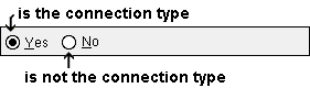
When ' Yes ' is selected, the condition may be true for beams on whose review windows the " System designed connection " for at least one end is a ' Clip angle '. When ' Member ' is selected as the item to be color coded , beams with system clip angles (either end) are color coded. When ' Ends ' is selected, only those beam ends that have a clip angle connection are color coded. When ' Left ' is selected, the left ends of beams that have a left-end clip angle connection are color coded.
When ' No ' is selected, the condition is true (regardless of whether ' Member ' or ' Ends ' or ' Left ' or ' Right ' is selected) for members (of any type) with connections other than clip angles on both ends.
Topics page: Clip Angle Connections
Beam window settings: Clip angle connection specifications
Connection design locks: NS Clip and others
Bent plate: Yes or No . Connection design can create bent plates for beams and horizontal braces. This search only finds beams bent plate system connections for beams.
When ' Yes ' is selected, the condition may be true for beams on whose review windows the " System designed connection " for at least one end is a ' Bent plate '. When ' Member ' is selected as the item to be color coded , beams with system bent plates (either end) are color coded. When ' Ends ' is selected, only those beam ends that have a bent plate connection are color coded. When ' Left ' is selected, the left ends of beams that have a left-end bent plate connection are color coded.
When ' No ' is selected, " the condition is true (regardless of whether ' Member ' or ' Ends ' or ' Left ' or ' Right ' is selected) for members (of any type) with connections other than bent plates on both ends.
Topics page: Bent Plate Connections
Beam window settings: Connection specifications
Connection design locks: Bent Plate and others
End plate: Yes or No . Connection design can create end plates for beams and braces. This search only finds beams that have end plate system connections .
When ' Yes ' is selected, the condition may be true for beams on whose review windows the " System designed connection " for at least one end is an ' End plate '. When ' Member ' is selected as the item to be color coded , beams with system end plates (either end) are color coded. When ' Ends ' is selected, only those beam ends that have an end plate are color coded. When ' Left ' is selected, the left ends of beams that have a left-end end plate are color coded.
When ' No ' is selected, the condition is true (regardless of whether ' Member ' or ' Ends ' or ' Left ' or ' Right ' is selected) for members (of any type) with connections other than end plates on both ends.
Topics page: End Plate Connection
Beam window settings: End plate connection specifications
Connection design locks: End Plate and others
Column base or cap plate: Yes or No . This search finds columns that have base or cap plate system connections .
When ' Yes ' is selected, the condition may be true for columns on whose review windows the " System designed connection " for at least one end is a ' Auto base/cap plate ' or ' User base/cap plate '. When ' Member ' is selected as the item to be color coded , columns with system base or cap plates (either end) are color coded. When ' Ends ' is selected, only those column ends that have base or cap plates are color coded. When ' Left ' is selected, the bottom ends of columns that have bottom-end base or cap plates are color coded.
When ' No ' is selected, the condition is true (regardless of whether ' Member ' or ' Ends ' or ' Left ' or ' Right ' is selected) for members (of any type) with connections other than column plates on both ends.
Topics pages: Auto Base/Cap Plate and User Base/Cap Plate
Connection specifications: Auto Base/Cap Plate and User Base/Cap Plate
Connection design locks (auto base/cap): Column Plate and others
Connection design locks (user base/cap): Column Plate and others
Shear: Yes or No .Connection design can create shear connections for beams and braces. This search only finds beams that have shear plate, tee or thru plate system connections .
|
When ' Yes ' is selected, the condition may be true for beams on whose review windows the " System designed connection " for at least one end is a ' Shear ' connection. When ' Member ' is selected as the item to be color coded , beams with shear connections (either end) are color coded. When ' Ends ' is selected, only those beam ends that have a shear connection are color coded. When ' Left ' is selected, the left ends of beams that have a left-end shear connection are color coded.
When ' No ' is selected, the condition is true (regardless of whether ' Member ' or ' Ends ' or ' Left ' or ' Right ' is selected) for members (of any type) with connections other than shear tabs, shear thru connections, shear moment connections, or shear tee connections on both ends.
Topics page: Shear Plate Connection
Beam window settings: Connection specifications
Connection design locks: Shear Tab and others
Seated: Yes or No . Connection design can create seated connections for beams and joists. This search only finds beams that have seated system connections .
When ' Yes ' is selected, the condition may be true for beams on whose review windows the " System designed connection " for at least one end is a ' Seated ' beam connection. When ' Member ' is selected as the item to be color coded , beams with seated connections (either end) are color coded. When ' Ends ' is selected, only those beam ends that have a seated connection are color coded. When ' Left ' is selected, the left ends of beams that have a left-end seated connection are color coded.
When ' No ' is selected, the condition is true (regardless of whether ' Member ' or ' Ends ' or ' Left ' or ' Right ' is selected) for members (of any type) with connections other than beam seats on both ends.
Topics page: Seated Beam Connection
Beam window settings: Connection specifications
Connection design locks: Seated Plate and others
Splice: Yes or No . This search finds beams and columns that have splice plate system connections . The search does not find end plate splices and clip angle splices.
When ' Yes ' is selected, the condition may be true for beams and columns on whose review windows the " System designed connection " for at least one end is a ' Splice ' connection. When ' Member ' is selected as the item to be color coded , members with splice plate connections (either end) are color coded. When ' Ends ' is selected, only those member ends that have a splice plate connection are color coded. When ' Left ' is selected, the left ends of members that have a left-end splice plate connection are color coded. A column's bottom end is its left end.
When ' No ' is selected, the condition is true (regardless of whether ' Member ' or ' Ends ' or ' Left ' or ' Right ' is selected) for members (of any type) with connections other than splice connections on both ends.
Topics pages: Beam Splice Connections and Column Splice Connections
Beam window settings: Connection specifications
Column window settings: Connection specifications
Connection design locks, beam: Web Plate and others
Connection design locks, column: Outer Flange Plate and others
Fully welded moment: Yes or No .
When ' Yes ' is selected, the condition may be true for beams on whose edit windows the " System designed connection " for at least one end is a ' Fully welded moment ' connection. When ' Member ' is selected as the item to be color coded , beams with fully welded moment connections (either end) are color coded. When ' Ends ' is selected, only those beam ends that have a fully welded moment connection are color coded. When ' Left ' is selected, the left ends of beams that have a left-end fully welded moment connection are color coded.
When ' No ' is selected, the condition is true (regardless of whether ' Member ' or ' Ends ' or ' Left ' or ' Right ' is selected) for members (of any type) with connections other than beam seats on both ends.
Also see: " Moment type " is automatically set to ' Welded ' when a beam's " Input connection type " is ' Fully welded moment '.
When ' Yes ' is selected, the condition may be true for vertical braces on whose review windows the " System designed connection " for at least one end is a ' Vbrc plate ' connection. When ' Member ' is selected as the item to be color coded , vertical braces with a ' Vbrc plate ' connection (either end) are color coded. When ' Ends ' is selected, only those vertical brace ends that have a ' Vbrc plate ' connection are color coded. When ' Left ' is selected, the left ends of vertical braces that have a left-end ' Vbrc plate ' connection are color coded.
When ' No ' is selected, the condition is true (regardless of whether ' Member ' or ' Ends ' or ' Left ' or ' Right ' is selected) for members (of any type) with connections other than vertical brace connections on both ends.
Topics page: 'Vbrc plate' connections
Beam window settings: Connection specifications
Connection design locks: Gusset One Member and others
When ' Yes ' is selected, the condition may be true for horizontal braces on whose review windows the " System designed connection " on at least one end is a ' Hbrc plate ' connection. When ' Member ' is selected as the item to be color coded , horizontal braces with a ' Hbrc plate ' connection (either end) are color coded. When ' Ends ' is selected, only those horizontal brace ends that have a ' Hbrc plate ' connection are color coded. When ' Left ' is selected, the left ends of horizontal braces that have a left-end ' Hbrc plate ' connection are color coded.
When ' No ' is selected, the condition is true (regardless of whether ' Member ' or ' Ends ' or ' Left ' or ' Right ' is selected) for members (of any type) with connections other than horizontal brace connections on both ends.
Topics page: 'Hbrc plate' connections
Beam window settings: Connection specifications
Connection design locks: Gusset One Member Square and others
User defined: Yes or No . User defined connections can be applied as an " Input connection type " to beams, columns, braces and joists.
When ' Yes ' is selected, the condition may be true for members on whose review windows the " Input connection type " on at least one end is a ' User defined ' connection. When ' Member ' is selected as the item to be color coded , members with a user defined connection (either end) are color coded. When ' Ends ' is selected, only those member ends that have a user defined connection are color coded. When ' Left ' is selected, the left ends of members that have a left-end user defined connection are color coded.
When ' No ' is selected, the condition is true (regardless of whether ' Member ' or ' Ends ' or ' Left ' or ' Right ' is selected) for members with connections other than user defined connections on both ends.
Job Setup: User Defined Connections
Specific user defined connection: Press the browse button ( ![]() ) and select the name of the user defined connection that you want.
) and select the name of the user defined connection that you want.
|
| The display logic shown here displays in red the ends of members with either of two similar user defined connections. The two conditions could be put into different priorities in order to have each member end with one or the other user defined connection displayed in a distinct color. |
When a name has been entered, the condition may be true for members that have that name entered as the " User defined connection " for at least one end on the beam , column , horizontal brace , vertical brace or joist windows. When ' Member ' is selected as the item to be color coded , members with the specific user defined connection (either end) are color coded. When ' Ends ' is selected, only those member ends that have the specific user defined connection are color coded. When ' Left ' is selected, the left ends of members that have the specific user defined connection on its left end are color coded.
More about the display logic in the example: If, in the example shown above, ' any ' were changed to ' all ', the statement would never be true since a member end can only have one user defined connection assigned to it at any one time. However, if ' Ends ' was then changed to ' Member '' along with ' any ' changed to ' all ', the statement would be true when a member has a user defined connection named EndPlate1 on its one end and a user defined connection named EndPlate2 on its other end.
Job Setup: User Defined Connections
|
|
| This example of a status priority would, since ' all ' is selected, color code members that have both an auto standard connection and an end plate connection. This priority would find two overlapping situations:1) beams with an end plate on one end and an auto standard connection on the other. 2) beams with auto standard end plates on either end or both ends. |
<When ' Yes ' is selected, the condition may be true for members on whose review windows the " Input connection type " is ' Auto standard ." Beams and columns and joists can have auto standard connections. When ' Member ' is selected as the item to be color coded , members with auto standard connections (either end) are color coded. When ' Ends ' is selected, only those member ends that have an auto standard connection are color coded. When ' Left ' is selected, the left ends of members that have an auto standard connection on its left end are color coded.
When ' No ' is selected, the condition is true (regardless of whether ' Member ' or ' Ends ' or ' Left ' or ' Right ' is selected) for members on whose review windows the " input connection type " is a choice other than ' Auto standard ' on both ends. It also is true for miscellaneous members and custom members.
Beam Review: Input connection type
Column Review: Input connection type
> model > | status display | status select | status (index) | top
------ Connection auto loads ------
Auto beam shear: Yes or No . When the display logic function is ' any ' or ' all ', this condition can color code or mask only beams . The ends of beams can be color coded, but not masked.
|
The condition and display logic shown here can color code ( aqua ) any beam ends with a user-entered " Shear load ." When ' Yes ' is selected, the condition may be true for beams whose " Shear load " on either end or both ends is set to "
When ' No ' is selected, the condition is true (regardless of whether ' Member ' or ' Ends ' or ' Left ' or ' Right ' is selected) for beams whose " Moment load " is set to "
Beam Review: Shear load
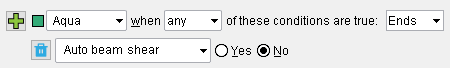
Auto beam moment: Yes or No . So long as the display logic function is a choice other than " none ," an auto beam moment condition (' Yes ' or ' No ') is able to color code beams only. The ends of beams can be color coded, but not masked.
Priority 1 color codes the ends of beams that have an auto moment load. Priority 2 color codes the ends of beams with a user-entered " Moment load ." When ' Yes ' is selected, the condition may be true for beams with a non-zero " Moment load " that is set to "
When ' No ' is selected, the condition is true for beams with non-zero " Moment load " that is set to "
Note: A beam has a non-zero " Moment load " when the " Moment type " is ' Bolted ' or ' Welded '. The " Moment load " is calculated regardless of whether the connection passes or fails.
Beam Edit: Moment load
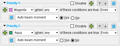
Auto column load: Yes or No . When the display logic function is ' any ' or ' all ', this condition can color code or mask columns . The ends of columns can be color coded, but not masked.
|  | ||||||||
When ' Yes ' is selected, the condition may be true for columns whose " Load " on either end or both ends is set to "
When ' No ' is selected, the condition is true (regardless of whether ' Member ' or ' Ends ' or ' Left ' or ' Right ' is selected) for columns whose " Load " on both ends is set to "
Column Review: Load
Auto column moment: Yes or No . When the display logic function is ' any ' or ' all ', this condition can color code or mask columns . The ends of columns can be color coded, but not masked.
| | ||||||||
When ' Yes ' is selected, the condition may be true for columns whose " Moment " load on either end or both ends is non-zero and set to "
When ' No ' is selected, the condition is true (regardless of whether ' Member ' or ' Ends ' or ' Left ' or ' Right ' is selected) for columns whose " Moment " on both ends is set to "
Note: A column can have a non-zero auto moment when the connection is a splice plate. For column connections other than splice plates, the auto moment is zero.
Column Review: Moment
Auto column splice uplift: Yes or No . When the display logic function is ' any ' or ' all ', this condition can color code or mask columns . The ends of columns can be color coded, but not masked.
| | ||||||||
When ' Yes ' is selected, the condition may be true for columns whose " Splice uplift " on either end or both ends is non-zero and set to "
When ' No ' is selected, the condition may be true for columns with splice plates whose auto splice uplift has been changed to "
Note: A column can have a non-zero auto splice uplift when the connection is a splice plate. For column connections other than splice plates, the auto splice uplift is zero.
Column Review: Splice uplift
Auto column horizontal shear: Yes or No . When the display logic function is ' any ' or ' all ', this condition can color code or mask columns . The ends of columns can be color coded, but not masked.
| | ||||||||
When ' Yes ' is selected, the condition may be true for columns whose " Horizontal shear " on either end or both ends is non-zero and set to "
When ' No ' is selected, the condition may be true for columns whose non-zero auto horizontal shear has been changed to "
Note: A column can have a non-zero auto horizontal shear when the connection is a splice plate with "
Column Review: Horizontal shear
Auto vertical brace tension: Yes or No . When the display logic function is ' any ' or ' all ', this condition can color code or mask only vertical braces .
| | ||||||||
When ' Yes ' is selected, the condition may be true for vertical braces whose " Tension load " on either end or both ends is set to "
When ' No ' is selected, the condition is true (regardless of whether ' Member ' or ' Ends ' or ' Left ' or ' Right ' is selected) for vertical braces whose " Tension load " on both ends is set to "
Vertical Brace Review: Tension load
Auto vertical brace compression: Yes or No . This condition, whether set to ' Yes ' or ' No ', can color code or mask members other than vertical braces only when ' none ' is the display logic function.
| | ||||||||
When ' Yes ' is selected, the condition may be true for vertical braces whose " Compression load " on either end or both ends is set to "
When ' No ' is selected, the condition is true (regardless of whether ' Member ' or ' Ends ' or ' Left ' or ' Right ' is selected) for vertical braces whose " Compression load " on both ends is set to "
Vertical Brace Review: Compression load
Auto horizontal brace tension: Yes or No . When the display logic function is ' any ' or ' all ', this condition can color code or mask only horizontal braces .
| | ||||||||
When ' Yes ' is selected, the condition may be true for horizontal braces whose " Tension load " on either end or both ends is set to "
When ' No ' is selected, the condition is true (regardless of whether ' Member ' or ' Ends ' or ' Left ' or ' Right ' is selected) for horizontal braces whose " Tension load " on both ends is set to "
Horizontal Brace Review: Tension load
Auto horizontal brace compression: Yes or No . This condition, whether set to ' Yes ' or ' No ', can color code or mask members other than horizontal braces only when ' none ' is the display logic function.
| | ||||||||
<When ' Yes ' is selected, the condition may be true for horizontal braces whose " Compression load " on either end or both ends is set to "
When ' No ' is selected, the condition is true (regardless of whether ' Member ' or ' Ends ' or ' Left ' or ' Right ' is selected) for horizontal braces whose " Compression load " on both ends is set to "
Horizontal Brace Review: Compression load
> model > | status display | status select | status (index) | top
 Activating/deactivating status display, saving files and reloading this window :
<
> ![]()
![]() or the Enter key closes the Status Display window (this window). So long as you remain in Modeling (do not exit), the Status Display window will remember the status display file settings that were most recently entered. If you exit Modeling then return and open Status Display again, the files on this window will be the files selected for User and Site Options > Modeling > " Status display criteria ."
or the Enter key closes the Status Display window (this window). So long as you remain in Modeling (do not exit), the Status Display window will remember the status display file settings that were most recently entered. If you exit Modeling then return and open Status Display again, the files on this window will be the files selected for User and Site Options > Modeling > " Status display criteria ."
If User and Site Options > Modeling > "
If "
Members/materials in your current erection view (as well as in views you subsequently Open ) will now be color coded, isolated or masked based on the conditions that are in each " Priority " that is defined in the active status display file .
The color-code key that you get when you press " Legend " remains open when you close Status Display .
The status display toggle will be set to on (
![]() (or the Esc key or the
(or the Esc key or the ![]() button) closes this window.
button) closes this window.
The active status display file will have no affect on display the model. That is to say, status display will be turned off in Modeling .
The status display toggle will be set to off (
Two ways to turn off status display in the 3D model: 1) Open this window then press the " Cancel " button. 2) Switch the status display toggle to off (
![]() automatically resets this window to those settings that were loaded when this window was first opened.
automatically resets this window to those settings that were loaded when this window was first opened.
![]() can be used to save all of the status display files shown on this window to any folder you like. You can even create a new folder for the files.
can be used to save all of the status display files shown on this window to any folder you like. You can even create a new folder for the files.
If the program detects that you will overwrite a file of the same name and that file is different than the file shown on this window, you will be prompted to overwrite or not.
By default, " Save... " accesses the
conf_status folder, but -- as mentioned above -- you are not limited to saving the file(s) into that folder.
![]() adds one or more new status display file(s) to this window as follows:
adds one or more new status display file(s) to this window as follows:
|
1 . A selection dialog opens. On it is a list of all status display files that are in the
2 . Select one or more file(s) that you want to load.
3 . The file(s) you selected in step 2 will be added to the file(s) that were already shown on this window.
Also see: Delete Status Configuration (a utility function)
![]() removes all status display files that are shown on this window and reloads the default status display file.
removes all status display files that are shown on this window and reloads the default status display file.
Example: Suppose that multiple condition statements are currently set on this window. Pressing this button will clear those statements so that only a single condition remains. You can then modify that statement as you please. This can simplify the editing of this window.
![]() applies the active status display file's status settings to your current view in the 3D model, but does not close this window. Members in your current view will be color coded, isolated or masked per the active file's display logic .
applies the active status display file's status settings to your current view in the 3D model, but does not close this window. Members in your current view will be color coded, isolated or masked per the active file's display logic .
Since this window remains open after you press " Apply ," you can make changes to this window and press the " Apply " button again to see what effect your changes will have on the model.
![]() gives you a color-code key the active status display file . The legend correlates which colors and priorities are assigned to which conditions. The legend remains open even after you close the Status Display window. A Status Display Legend icon can be added to a toolbar in Modeling to give you this same functionality without your having to open this window.
gives you a color-code key the active status display file . The legend correlates which colors and priorities are assigned to which conditions. The legend remains open even after you close the Status Display window. A Status Display Legend icon can be added to a toolbar in Modeling to give you this same functionality without your having to open this window.
|
 |
| The file name of the active status display file summarized in this legend is "PlateThickness." Priority 1 colors plate material cyan. Priority 2 colors plate material orange. The " OK " button closes the legend. |
> model > | status display | status select | status (index) | top