"  Column Web Doubler " connection design locks
| " |
|
|||||
|
"
 |
|
||||
|
|||||
Connection Guide: Click here or here for sample screen shots.
User Defined Connections: Settings that are locked (
) in a user defined connection file will automatically be locked on a member edit window for which that file is the " Input connection type ." You can, if you so choose, manually lock additional settings on the member edit window, and your changes will be retained, through multiple processes, so long as you do not change to a different connection then switch back to the original user defined connection.
Beam Edit: To change a setting, first set it to locked (
). Related settings that are unlocked (
) may be updated, and the "
Left/Right end limit state " calculations will be updated. Settings that are locked (
) will not be changed by connection design , even if doing so might prevent a connection failure.
Connection design locks :
| Locks not dimensioned or called out on the drawing are marked ( not depicted ). |
![]() Column Web Doublers
Column Web Doublers
NS and/or FS plate(s)
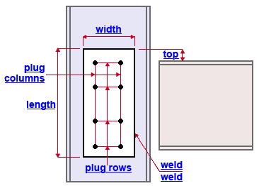
Top of plate ( top ): The positive (+) or negative (-) distance (parallel with the work line of the column) from the top edge of the column web doubler plate to the top flange of the supported beam. A positive (+) distance places top edge of the web doubler plate that distance below the top flange of the supported beam. A negative (-) distance places the top edge of the web doubler plate that distance above the top flange of the supported beam. In the example shown, this distance is negative.
Plate length ( length ): The distance (parallel with the work line of the column) between the top edge and bottom edge of the column web doubler (see example ). If the column is vertical, this distance is vertical. Note: " Top of plate " positions the top edge of the web doubler plate.
Plate width ( width ): The distance (perpendicular to the work line of the column) between the edges of the column web doubler that are parallel with the work line of the column (see example ). If the column is vertical, this distance is horizontal. A column web doubler that is unlocked (
) is designed so that its vertical edges are in alingment with the design k distance from the column flange.
End connection failure message: Column web doubler width does not fit column
Plate thickness ( not depicted ): The " Material thickness " of the column web doubler plate(s).
End connection failure message: Column web doubler thickness less than minimum required
End connection failure message: Column web panel failed in shearWeld size ( weld ): The weld size for shop welding the doubler plate to the column web.
End connection failure message: Column web doubler weld size less than minimum required
Plug diameter ( not depicted ): The diameter of the plug weld holes. Tip: If you don't want plug weld holes, set the " Plug rows " or " Plug columns " to ' 0 '. If you set this to zero, you may get CNC marks.
Plug rows: The number of rows of holes. Hole row spacing runs parallel with the column work line, vertically for a perfectly vertical column. In the example shown, this number is ' 4 '.
Plug columns: The number of columns of holes. Assuming the column is perfectly vertical, the plug hole column spacing will run horizontally. In the example shown, this number is ' 2 '.


