Connection Guide : Moment Connections
| Disclaimer: This guide is not comprehensive. It shows only a few of the many moment connections that connection design can create. |
| Moment Connections | ||
| With flange angles | Sloping, bolted (clip L) | Beam-to-beam |
| With flange plates | Sloping, bolted (col slopes) | HSS column reinforcement |
| Bolted, to a column flange | Sloping, welded (shear plate) | AISC End Plates |
| Bolted, to a column web | Sloping, welded (clip L) | Sloping moment end plate |
| Bolted, to a HSS rectangular column | Sloping, welded (col slopes) | MBMA end plates |
| Bolted, to a HSS round column | Sloping, welded, to web | End plate splices |
| Cap plates | Welded, to web (col slopes) | Moment beam splice plates |
| Welded, to flange (or a HSS rectangular) | Bolted, to column web | Splice w/ inner flange plates |
| Welded, to a column web | Bolted, to web (col slopes) | Fully welded moment |
| Sloping, bolted (shear plate) | Bolted, skewed to column | |
Also see :
- Moment settings ( Beam Edit window)
- Setup for moment connections (index)
- Preferred Angle Sizes (setup list for moment flange angles)
- Welded moment flange plates ( Home > Project Settings > Job > Moment Plate Design Settings )
- Bolted Moment Flange Plate Gap ( Home > Project Settings > Job )
- Design depth ( Home > Project Settings > Job > Moment Plate Design Settings > " To Column Flange " tab > " Flange stiffeners " heading > )
- Moment connection welds ( Home > Project Settings > Job > Weld Design Settings )
- Ways of generating connections in Modeling (topics)
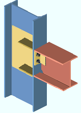
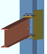
| Clip Angle Moment Connection with Flange Angles | |
| Connection Design Locks = " NS Clip ," " FS Clip ," " Top Moment Angle ," " Bottom Moment Angle " | |
| Settings: ' Clip angle ', ' Bolted ' connection with ' Angle ', " Doublers " (not checked) or " Stiffeners " (not checked). |
|
| Framing situations: W or S or welded plate W beam perpendicular to a W or S or welded plate W column flange or HSS rectangular column. | |
| Comments: Angles must be in the " Preferred Angle Sizes " list. | |
Moment Connections with Bolted Flange Plates
| Clip Angle Moment Connection with Flange Plates | |
| Connection Design Locks = " NS Clip ," " FS Clip ," " Top Moment Plate ," " Bottom Moment Plate " | |
|
Settings: ' Clip angle ', ' Bolted ' connection with ' Plate ', " Doublers " (not checked) and " Stiffeners " (not checked); " Gap " (setup). |
| Framing situations: W or S or welded plate W beam perpendicular to a W or S or welded plate W column flange or HSS rectangular column. | |
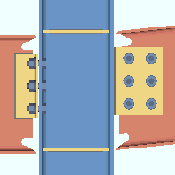
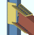
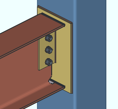
| Shear Plate Bolted Moment Connection to a Column Flange | |
| Connection Design Locks = " Shear Tab ," " Top Moment Plate ," " Bottom Moment Plate ," " Column Flange Stiffeners " | |
| Settings: ' Shear ', ' Bolted ' connection with ' Plate ', " Doublers " (checked) and " Stiffeners " (checked); " Gap " (setup). |
|
| Framing situations: Shear plate on W or S beam to a column flange (shown). | |
| Also possible: Shear plate bolted moment connections to column or beam webs. | |
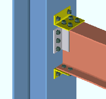
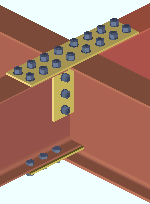
| Bolted Moment Connection to a Column Web | |
| Connection Design Locks = " Shear Tab ," " Top Moment Plate ," " Bottom Moment Plate " | |
|
Settings: ' Shear ' (shown) or ' Clip angle ' (not shown), ' Bolted ' connection with ' Plate ', " Gap " (setup). |
| Framing situations: W or S or welded plate W beam framing to a column web. | |
| Note: The flange plates weld to both the web and flanges of the column. | |
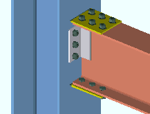
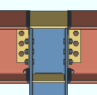
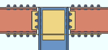
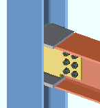
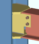
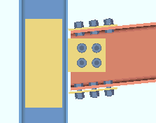
| Bolted Moment Connection to an HSS Rectangular Column | |
| Connection Design Locks = " Shear Tab ," " Top Moment Plate ," " Bottom Moment Plate " | |
| Settings: ' Shear ' (shown) or ' Clip angle ' (not shown), ' Bolted ' connection with ' Plate ', " Gap " (setup).
|

|
| Framing situations: W beam framing to a HSS rectangular column. Skewed framing situations are not supported to HSS rectangular columns -- they are supported to wide flange . | |
| Connections on sloping beams or to sloping columns can be created at angles up to 30 degrees. The connection fails if the beam's workline is not in the same plane as the column workline or does not go to the center of the column. |

|
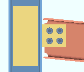
| Bolted Moment Connections to an HSS Round Column | |
| Connection Design Locks = " Shear Tab ," " Top Moment Plate ," " Bottom Moment Plate " | |
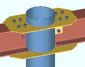
|
Settings: ' Shear ' (shown) or ' Clip angle ' (not shown), ' Bolted ' connection with ' Plate ," " Gap " (setup). |
| Framing situations: W beam framing to a HSS round column. | |

|
Connections on sloping beams or to sloping columns can be created at angles up to 30 degrees. The connection fails if the beam's workline is not in the same plane as the column workline or does not go to the center of the column. |
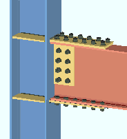
| Welded Moment Cap Plate | |
| Connection Design Locks = " NS Clip ," " FS Clip ," " Moment Cap Plate ," " Column Flange Stiffeners " | |
| Input connection type: ' Clip angle ' (shown) or ' Shear ' (not shown) or ' User defined '.
|
|
| Settings: " Moment type " (' Welded ') | |
| Comments: Connection design creates a moment cap plate when at least one beam with a welded moment connection frames to the top of a column flange. The " |
|
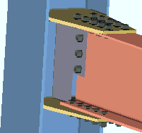
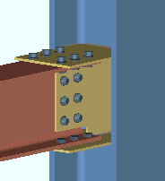
| Bolted Moment Cap Plate | |
| Connection Design Locks = " NS Clip ," " FS Clip ," " Top Moment Plate ," " Bottom Moment Plate ," " Column Web Doublers ," " Column Flange Stiffeners " | |
|
|
| Settings: ' Clip angle ' (shown) or ' Shear ' (not shown), ' Bolted ' moment connection with ' Plate '. ' Plain end ' on the column. | |
| Comments: The top bolted moment flange plates combine to form a single cap plate that shop welds to the column. To get this connection, the wide flange beams must be colinear, at the elevation of the top of the column, and horizontal. The " |
| Here's a similar connection. In this case, the beam has a joist framing opposite to it instead of another beam. Like in the example above, the top moment flange plate extends to form a cap plate that welds to the column. |
|
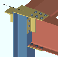
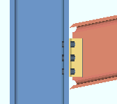
| Welded Moment Connection to a Column Flange | |
| Connection Design Locks = " NS Clip ," " FS Clip ," " Column Web Doublers ," " Column Flange Stiffeners " | |
|
Settings: ' Clip angle ' (shown) or ' Shear ' (not shown), ' Welded ' connection, ' Alternate 1 ' " Re-entrant cut ." |
| Framing situations: W beam or S or welded plate W beam perpendicular or sloping to a W or S or welded plate W column flange. Weld prep can also be designed to a HSS rectangular column. | |
| Note: " Doublers " and " Stiffeners " are optional, but not for HSS rectangular columns. | |
|
#1 Welded Moment Connection to Column Flange. Framing situations and settings required to generate these connections are described above . Note that one of the connections has a shear plate, the other a clip angle. Also note that the right beam is sloping. |
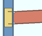
| Welded Moment to a Column Web (shear tab) | |
| Connection Design Locks = " Shear Tab ," " Top Moment Plate ," " Bottom Moment Plate " | |
| Settings: ' Shear ', ' Welded ' connection.
|
|
| Framing situations: Beam to a column web. | |
| Comments: Welded moment stiffener plates (shown in gray) shop weld to the column and field weld to the beam flanges. | |
| Here's a similar connection. In this case, the view shows the welding end preparation on the beam. The example below shows this same connection in an isometric view. |

|
| The same connection as above. In this case, the connection is shown in an isometric view. Note that the top and bottom moment plates are tapered so that their edges are the same width as the beam's flanges. Setup options control the " Plate extension " " Top location " " Bottom location " and " Corner operation " on these plates. |
|
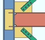
| Sloping Bolted Moment Connection (shear plate) | |
| Connection Design Locks = " Shear Tab ," " Top Moment Plate ," " Bottom Moment Plate ," " Column Web Doublers " | |
|
Settings: A ' Shear ' connection with ' Bolted ' moment ' Plates ' and " Doublers " (checked). The " Gap " is specified at Home > Project Settings > Job > Flange Plate Clearances . |
| Framing situations: W or S or welded plate W beam sloping up to 30 degrees to a column flange. | |

|
Sloping bolted moment connection with clip angles: In this example, a ' Clip angle ' is ' Welded ' (to supported) on ' Both sides ' of the beam web, ' Bolted ' (to the supporting column flange), and has ' Bolted ' moment ' Plates '. |

|
Bolted moment connection to sloping column: A non-sloping beam to a sloping column is shown. The beam could also be sloping. Exception: " Connection to sloping column not supported " |
|
Sloping Welded Moment to a Wide Flange Column Flange
or to an HSS Rectangular Column |
|
| Connection Design Locks = " Shear Tab ," " Column Web Doublers " | |
| Settings: ' Shear ' (shown) or ' Clip angle ' (not shown), ' Welded ' connection, " Doublers " (checked). |
|
| Framing situations: Beam sloping up to 30 degrees to a column flange or to a HSS rectangular column. | |
| Sloping welded moment connection with clip angles: In this example, a ' Clip angle ' is ' Welded ' (to supported) on ' Both sides ' of beam web, ' Bolted ' (to supporting) and has a ' Welded ' moment connection. |
|
|
Welded moment connection to a sloping column: A non-sloping beam to a sloping column is shown. The beam could also be sloping. Exception: " Connection to sloping column not supported " |

|
| Sloping Welded Moment Connection to a Column Web | |
| Connection Design Locks = " Shear Tab ," " Top Moment Plate ," " Bottom Moment Plate " | |

|
Settings: ' Shear ', ' Welded '. Flange plates in the column web field weld to the beam flanges. |
| Framing situations: The beam can slope up to 30 degrees. | |

|
Welded moment connection to a sloping column's web: A non-sloping beam to a sloping column is shown. The beam could also be sloping. Exception: " Connection to sloping column not supported ." |
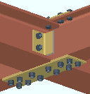
| Bolted Moment Connection on Column Web | |
| Connection Design Locks = " Shear Tab ," " Top Moment Plate ," " Bottom Moment Plate " | |
| Settings: ' Shear ', ' Bolted '. |
|
| Framing situations: Beam to the web of a W column. | |
| Comments: The top and bottom moment plates weld to the flanges and web of the column. | |
| Bolted moment connection to sloping column's web: A non-sloping beam to a sloping column is shown. The beam could also be sloping. Exception: " Connection to sloping column not supported ." |

|
| Bolted Moment Connection on Beam Skewed to a Column | |
| Connection Design Locks = " Shear Tab ," " Top Moment Plate ," " Bottom Moment Plate " | |
|
Settings: ' Shear ', ' Bolted '. |
| Framing situations: W or S or welded plate W beam skewed to a column flange or web. | |
| Comments: The design of this connection can vary widely depending on the angle of skew and the part of the column that the beam frames to. | |
|
Another example of a skewed moment connection. The web plate on the column is generated automatically so that the bolted moment flange plate has something to weld to. |
| Beam-to-Beam Moment Connection | |
| Settings: ' Shear ' (shown) or ' Clip angle ' (not shown), ' Bolted ' moment, flange plates on ' This ' (or ' Opposite ') member. |
|
| Comments: Top flanges of the two opposing beams must be at the same elevation. If the center beam is deeper than the two beams (as shown), the bottom flange plates weld to the center beam's web. The " Moment load " on opposing beams must be of equal, but with opposite signs. | |
| An example of a beam-to-beam welded moment connection. End connection failure messages for beam-to-beam moment connections are: " Beam to beam moment conn must have a member opposite ," " Moments at conn must be equal but opposite sign ," " Both beams at connection must have same moment type ," " Incompatible member sizes ." |

|
| Here's an example of a bolted beam-to-beam moment connection with clip angles. You can have a clip angle on the one supported beam and a shear plate on the opposing beam. Fill plates are designed if the depth of the supported beam is less than the supporting beam. |
|
| HSS Column Reinforcement Plate Opposite a Welded Moment | |
| Connection Design Locks = " Column Reinf Plate " | |
| Input connection type: ' Shear ' or ' User defined '.
|
|
| Settings: " Use HSS column reinforcement plate " (' Yes ' or ' Automatic '), " Moment type " (' Welded ') | |
| Comments: Connection design creates a plate only if it is needed to reinforce the thin-walled HSS column. A reinforcement plate may also be designed for a simple single-plate shear connection. | |
| AISC Moment End Plates |
| Connection Design Locks = " Moment End Plate " " Moment Stiffeners " |
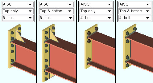
|
| Settings: ' End plate ' as the " Input connection type ," ' Bolted ' as the moment connection type. Other settings are shown in the illustrations above. Also, the end plates that are shown are only a few of the AISC moment end plates that connection design can create. |
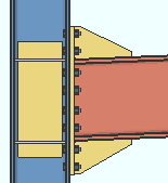
| Sloping Moment End Plate (AISC 8-bolt shown) | |
| Connection Design Locks = " Moment End Plate " " Moment Stiffeners " | |
|
Input connection type: ' End plate ' or ' User defined '. |
| Settings: ' Bolted ' moment. | |
| Comments: Beginning with v2018, a moment end plate can be designed on the end of a sloping beam or to a sloping column. | |
|
In this example of a sloping moment end plate, the column slopes and the beam is horizontal. |
|
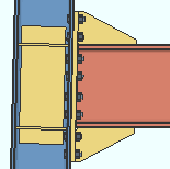
| MBMA Moment End Plates |
| Connection Design Locks = " Moment End Plate " " Moment Stiffeners " |
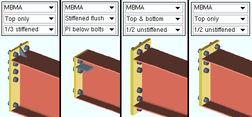
|
| Settings: ' End plate ' as the " Input connection type ," ' Bolted ' as the moment connection type. Other settings are shown in the illustrations above. Also, the end plates that are shown are only a few of the MBMA moment end plates that connection design can create. |
| Moment End Plate Splices (AISC 8-bolt shown) | |
| Connection Design Locks = " Moment End Plate " " Moment Stiffeners " | |
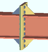
|
Input connection type: ' End plate ' or ' User defined '. |
| Settings: ' Bolted ' moment. | |
| Comments: The beams must be colinear W or S sections. The sections must be the same size and the top flanges at the same elevation. | |
| Moment Beam Splice Plates | |
| Connection Design Locks = " Web Plate ," " Moment Flange Plate " | |
| Input connection type: ' Splice plate ' or ' User defined '.
|
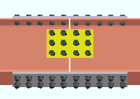
|
| Settings: ' Bolted ' moment, " Plates on " (any choice). | |
| Comments: Both beams must be colinear and use wide flange or welded plate wide flange " Section sizes " with depths that are less than 1.25 inches in difference. | |
| Beam Splice with Moment Flange Plates and Inner Flange Plates | |
| Connection Design Locks = " Web Plate ," " Moment Flange Plate " " Filler Plate " " Inner Flange Filler Plate " | |
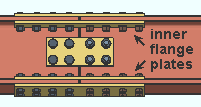
|
Input connection type: ' Splice plate '. |
| Settings: ' Bolted ' moment, " Plates on ," " Use inner flange plates " (' Yes ' or possibly ' Automatic '). | |
| Comments: Top and bottom inner flange plates can be employed when top and bottom moment flange plates are used. | |
|
||
|
||
| Input connection type: ' Fully welded moment connection ' or ' User defined '.
|

|
|
| Comments: Selecting this input connection type automatically sets the " Moment type " to ' Welded '. A clip angle or shear plate or bent plate is not a part of the connection. " Doublers " and " Stiffeners " are optional. The web and flange welds are field welds. | ||
|
| A vertical brace to a beam with a fully welded moment connection that frames to a column can get a designed connection. |
|
|
| A beam with a fully welded moment connection can frame sloped to a column. |
|

