 Layer Panel
Layer settings and tools for your current drawing.
- General Overview
- Tips and Tricks
- Related Tools
Layer Panel button: Press this button to collapse and expand the Layer Panel.
The Layer Edit All command also expands the Layer Panel when it is collapsed, and switches to the Layer Panel when the Drawing List Panel or the Drawing Data Panel is open.
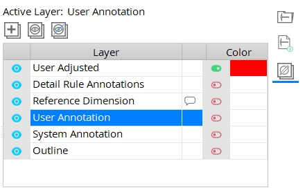
Active Layer: This is your currently selected layer. When you add new objects to the drawing, they are added to the Active Layer. The default Active Layer for most types of drawings is the User Annotation layer.
Note: The Active Layer is also reported on the bottom of the Drawing Editor window at all times.
![]() Layer Add: Adds a new layer row to the table. See Layer Add for additional information.
Layer Add: Adds a new layer row to the table. See Layer Add for additional information.
Tip: You can also right-click anywhere on the panel and select Layer Add from the menu.
![]() Layer Show All: Changes all
Layer Show All: Changes all  hidden layers to be
  shown. See Layer Show All for additional information.
Tip: You can also right-click anywhere on the panel and select Layer Show All from the menu.
![]() Layer Hide All: Changes all shown layers to be hidden.
Layer Hide All: Changes all shown layers to be hidden.
Tip: You can also right-click a specific layer and select Layer Hide Others from the menu to hide all other layers except the one you right-clicked.
/ Layer Show/Hide: Show or hide individual layers by left-clicking the icon. The hidden/shown state of layers is retained when you Save the drawing.
When the layer is
When the layer is
Tip: You can also right-click on a layer and select Layer Show or Layer Hide from the menu.
Layers are selectable. The graphic object(s) you add to the drawing will be added to the selected layer.
The listed order of the layers can be changed. Select a layer, hold down the left-click button on your mouse, and drag the layer up or down on the list.
Edit a layer's name by double-clicking it.
Delete layers by right-clicking and selecting Layer Erase or Layer Erase All from the menu.
Default layers are added to drawings during automatic detailing.
The layer names also populate the selection menus on graphic object edit windows.
Default Layers
User Adjusted: The User Adjusted layer includes the graphic objects that were created for annotation purposes during auto detailing, but were modified by a user in a way that changed their meaning. When a user edits a hole symbol, dimension, weld symbol, or bevel symbol that is on a System Annotation layer, that object is automatically moved to the User Adjusted layer. Making cosmetic changes does not move the object to the User Adjusted layer. For example, changing an object's font size or pen number or location does not move it to the User Adjusted layer. Making a change that alters the information conveyed by the annotation (e.g., changing text on a weld symbol, label, hole symbol, or dimension) does move the object to the User Adjusted layer.
Detail Rule Annotations: The Detail Rule Annotations layer includes the graphic objects that were created by a template detailing during auto detailing using templates.
Reference Dimension: Reference dimensions may be placed onto a Reference Dimension comment layer by template detailing during auto detailing using templates. These dimensions are placed on the System Annotation layer when not using detailing templates. Since the Reference Dimension layer is a comment layer, dimensions on that layer will print only if you choose to
Plot comment layers when exporting to PDF (or plotting). To move a dimension to the Reference Dimension layer, select the dimension's Layer on its Edit Dimension window. Some detailers move extra system dimensions to the Reference Dimension layer instead of deleting them since such dimensions may be of use to checkers even though shop personnel might see them as unneeded clutter.
User Annotation: The User Annotation layer typically contains graphic objects that a user has added to a drawing. When you first open a drawing that was created by auto detailing, the User Annotation layer is automatically selected. By default, users will add new drawing annotations to this layer unless a different layer has been selected.
System Annotation: The System Annotation layer typically contains graphic objects that auto detailing has added to annotate materials that are shown on the Outline layer. You can find a System Annotation layer on member details, erection view drawings, and submaterial details (drawing types that are created by auto detailing).
Outline: The Outline layer typically contains the material polygons of system-generated material that is depicted on the drawing. You can find an Outline layer on member details, erection view drawings, and submaterial details.
Revision: The Revision layer is where auto detailing adds clouds and revision deltas to drawing changes.
Example of a cloud and pointer and delta symbol that might be found on a revision layer. Changes to details are clouded on this layer according to Home > Project Settings > Fabricator > Sheet Revisions > Method to be used for clouding changes on details. The clouds are drawn around differences between the base drawing and the new drawing.
Detail Members automatically generates a layer with this name for selected members when Detail with revisions is checked. Such a layer is also created when Detail with revisions is checked for submaterial and when Detail with revisions is selected for Detail Erection Views.
Plot revision layers can be toggled when you use Plotting or Export PDF Drawing. Print PDF will show Revision Layers if they are set to Shown.
 Comment Layer: This symbol tells you the layer is a Comment Layer.
Comment Layers are visible in Drawing Editor, but not on printed or PDF drawings unless Plot comment layers is checked
You cannot change a comment layer to a non-comment layer or vice-versa. To move objects from a comment layer to a non-comment layer, first select the objects that are on the comment layer. Right-click and select Edit from the context menu. Then, select a non-comment layer from the Layer menu shown in edit window that opens.
Tip: You can add a new Comment Layer by right-clicking anywhere on the panel and selecting Add Comment Layer from the menu, or by using the Layer Add command.
Color: Click the color swatch to launch your operating system's color picker to select a display color for the objects on that layer.
When set to
active, all graphic objects on that layer are displayed in the selected color if User and Site Options > Drawings >Show layer colors in Drawing Editor
When set to
inactive, the graphic objects are displayed in their normal pen colors.
Project Settings: The Drawing Presentation > Fabricator > Detailing > Drawing Presentation > Colors page sets default colors for layers created during auto detailing and for new layers you add to the drawing.
- A layer is a means of grouping objects on a drawing. Each object in a drawing is on the one layer that is specified on that object's edit window.
- Right-click options on the Layer Panel:
Layer Show
Layer Hide
Layer Hide Others
Layer Show All
Layer Add
Add Comment Layer
Layer Erase
Layer Erase All - The show/hide state of layers is retained when you save the drawing.
- Hidden layers are not plotted.
- If Freeze drawing is checked for a member detail, you are limited to adding graphics to comment layers while in that drawing.
- You can undo changes made to layers using Revert or Undo. If you Save your changes, you can no longer Revert, but you can still Undo.
- Layers on drawings are Plotted in order. The bottom layer is plotted first. The top layer is plotted last. It is generally desirable to place opaque objects such as objects with a hatch or fill on lower layers. For example, if a label is on a layer that is below a layer that has an image on it, you might want to move the image's layer down so that the label will print above the image.

