The Stair Treads setup window ( Fabricator Settings ) (read-only)
| Settings on this window tell you how this window has been set up for this Fabricator in a full-featured SDS2 program . |
Step-by-step instructions
1 . Open this window
2 . Select a definition
3 . Each tread definition has a type .
4 . Close this windowPan
--- "Type of tread" = 'Pan'
--- Shape
--- Thickness and Grade
--- Nosing
--- Pan
--- Tread support
--- RemarksGrating
--- "Type of tread" = 'Grating'
--- Bearing bars
--- Cross bars
--- Holes
--- End plates
--- RemarksPlate
--- "Type of tread" = 'Plate'
--- Shape
--- C-shaped (up and down)
--- Cold formed channel
--- Other
--- Rolled channel
--- Rolled cold formed channel
--- Tread support
--- Holes
--- RemarksContinuous
--- "Type of tread" = 'Continuous'
--- Tread settings
--- Tread support
--- Remarks
Also see :
- Stair Review window (where a stair tread definition is applied)
- Grating Tread Material (a material window)
contents | home > project settings > fabricator > | classic
1 . Open the Stair Treads window using any one (1) of the following methods:
Method 1 : Home > Project Settings > Fabricator > Stair Treads .
Methods 2, 3 & 4 : In Modeling or the Drawing Editor , choose Settings > Fabricator Settings > Stair Treads (classic), or use a keyboard shortcut , or click the icon.
2 . The Stair Treads window opens. A selection widget of 16 tread definitions runs along the left edge of the window.
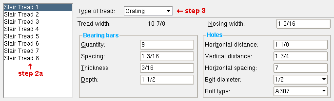
2a : Select the stair tread definition (1 through 16) that you want to review.
3 . The tread definition that you selected in 2a has a " Type of tread " and a " Name ."
Type of tread: ' Pan ' or ' Grating ' or ' Plate ' or ' Continuous ' may be the selected " Type of tread ."
![]()
If ' Pan ' is selected , see Bent Pan Stair Tread for further information.
If ' Grating ' is selected , see Grating Stair Tread for further information.
If ' Plate ' is selected , see Plate Tread Setup for further information.
If ' Continuous ' is selected , see Continuous Stair Tread for further information.
Name: A string of up to 30 characters. Within your current Job and current Fabricator, all references to the particular tread definition that you are reviewing is the name that is entered here.
Original name: User-entered name:
Stair tread 2
Bolted Grating For example, the name that is entered here is also the tread definition name that is currently selected on this window's tread definition selection widget (step 2).
The name that is entered here may also be shown in the list boxes for " Intermediate tread schedule " and " Top tread schedule " and " Bottom tread schedule " on the Stair Review window.
4 . When you are done reviewing the tread definition you selected in step 2a ...
Alternative 1 : Repeat these instructions beginning with step 2.
Alternative 2 : Press the " OK " button to close Stair Treads .
page 1 | contents | home > project settings > fabricator > | classic | top
Bent Pan Stair Tread
Type of tread: Pan or Grating or Plate or Continuous .
When ' Pan ' is selected, the following fields will be active.
For ' Grating ', see Grating Stair Tread .
For ' Plate ', see Plate Stair Tread .
For ' Continuous ', see Continuous Stair Tread .
Name: See " Name ."
| Shape: |
|
|
|
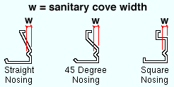
| Description: | straight nosing with no bend | straight nosing with back bend | straight nosing with sanitary cove |
| Shape: |
|
|
|
| Description: | beveled nosing with no bend | beveled nosing with back bend | beveled nosing with sanitary cove |
| Shape: |
|
- |
|
| Description: | 45 degree nosing with no bend | - | 45 degree nosing with sanitary cove |
| Shape: |
|
- |
|
| Description: | square nosing with no bend | - | square nosing with sanitary cove |
| Note: After selecting the shape that you want, make appropriate entries for options under " Thickness " " Nosing " " Pan " and " Tread support ." The " Sanitary cove width " field only applies to shapes with a sanitary cove. |
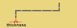
Plate thickness: The thickness (in the primary dimension " Units " or in other units ) of the plate used for the bent pan stair tread.
Gage plate : If, for example, ' 4GA ' is entered here, then this is a gage plate. Allowable gages are any whole number from 3 to 38. The " Description " for a gage plate follows the format: ' plate type prefix ' + ' numberGA ' + ' x ' + ' width ' (example: PL16GAx15 1/2 ).
Grade: A36 or A572 or etc. The grade of steel for the bent plate layout material that is used to model the pan treads.
Setup: Steel grades for multi-bend plate material are defined at Home > Project Settings > Job > Plate Grades .
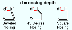
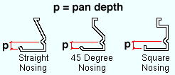
Depth: The vertical distance (in the primary dimension " Units " or in other units ) from the top of the nosing return to the first bend.
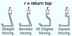
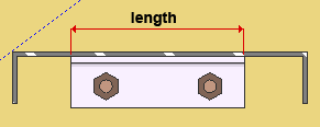
Return top: The horizontal distance (in the primary dimension " Units " or in other units ) from the top nosing bend to the nearest vertical edge. In other words, this is the length of the top edge of the nosing.
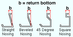
Return bottom: The horizontal distance (in the primary dimension " Units " or in other units ) from the top nosing bend to the main bend or the first intermediary bend.
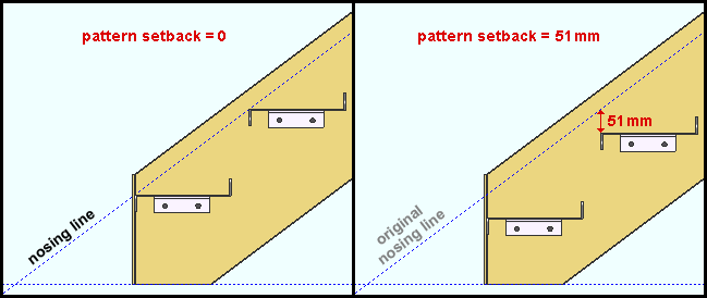
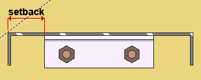
Abrasive setback: The distance ( vertical ) (in the primary dimension " Units " or other units ) that the pan treads are offset from the workline of the stair. An " Abrasive setback " of ' 0 ' aligns the nosing line with the workline of the stair. Typically an " Abrasive setback " is applied in order to model the space that is needed to accommodate abrasive nosing material.
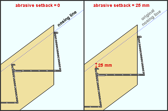
|
| In the right example, the " Abrasive setback " is 25 mm (1 inch), which is a very large distance given the typical purpose for which the " Abrasive setback " is provided. The setback was made so large in this example so that you could more easily see it. |
Depth: The vertical distance (in the primary dimension " Units " or in other units ) from the top of the pan to the top of the adjacent nosing return (as illustrated below).
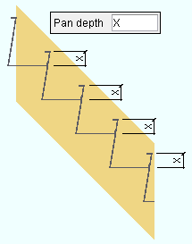
A special case: For a pan with a sanitary cove, this is the vertical distance from the top of the pan to the inside (middle) bend of the sanitary cove.
|
| The " Pan depth " and " Sanitary cove width " together position the sanitary cove. |
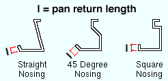
Return length: The actual distance (in the primary dimension " Units " or in other units ) from the pan return bend to the top edge of the pan return.
Sanitary cove width: The horizontal distance (in the primary dimensioning " Units ") from the sanitary cove's inside bend to its upper bend. A value of 0 (zero) means there is no sanitary cove.
Type: None or Single support or Dual supports or Bent plate . For a choice other than ' None ', an appropriate choice needs to be made to " Material description ."
None
|
Single support
|
Dual supports
|
Bent plate
|
' None ' instructs a full-featured SDS2 program to not generate support material for the bent pan treads.
' Single support ' results in a single support (angle, plate, bar) for each side (NS and FS) of each tread. The " Material description " (below) sets whether the support is an angle, plate or bar and also specifies the thickness and width of the support. The positioning and length of the support is calculated automatically and can be reviewed under " Tread support settings " on a Stair Review window in which this tread definition is specified.
' Dual supports ' results in two angles, plates or bars for each side of the pan (NS and FS), one to support the pan, the other to support the riser. The " Material description " (below) sets whether the supports are angles, plates or bars and also specifies the thickness and width of the supports. The positioning and length of the supports is calculated automatically based on the tread geometry and can be reviewed under " Tread support settings " on a Stair Review window in which this tread definition is specified.
' Bent plate ' results in a NS bent plate and FS bent plate as supports for each pan tread. The " Material description " (below) sets the width and thickness of the bent plate. The " Dimension tread face " together with the " Dimension riser face " set the length of the bent plate.
Material description: An angle section size ( angle ) or plate description ( plate ) or flat bar description ( flat bar ) or bent plate description . This applies when ' Single support or ' Dual supports has been selected as the " Tread support type ."
An angle section size must be a material that is available in the local shape file (e.g. L1x1x1/8).
A plate description is designated by the "Plate" prefix + thickness x width. For example, PL1/4x1, where PL is the plate prefix.
A flat bar description is designated by the "Flat bar" prefix + thickness x width. For example, FL1/4x1, where FL is the flat bar prefix.
A bent plate description can be a flat bar description (e.g. FL1/8x1) or a plate description (e.g. PL 1/8x1). Either description results in a bent plate being generated in the model. The " Material length " and " Material thickness " of the bent plate is specified in this description.
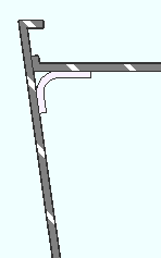
Dimension tread face: The distance ( horizontal ) (in the primary dimension " Units " or other units ) from the inside face of the riser to the end of the bent plate leg that attaches to the tread. This applies when ' Bent plate ' is selected as the " Type " of pan tread support. On the bent plate material in the model, the " Dimension tread face " is the " Length leg 1 " of the bent plate.
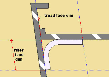
Dimension riser face: The distance ( diagonal ) (in the primary dimension " Units " or other units ) from the end of the bent plate leg that attaches to the riser to the heel of the tread. This applies when ' Bent plate ' is selected as the " Type " of pan tread support. The " Dimension riser face " is measured parallel with the riser. On the bent plate material in the model, the " Dimension riser face " is the " Length leg 2 " of the bent plate.
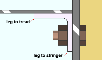
Long leg to: Stringer or Tread . This applies when an angle with unequal legs has been entered as the " Material description ." If the legs of the angle are equal, the choice made here does not matter.
' Stringer ' designates at the long leg of the angle is the leg that bolts to the stringer. The leg to stringer is the vertical leg in the installed angle.
' Tread ' designates that the long leg of the angle is the leg that supports the tread. The leg to tread is the horizontal leg in the installed angle.
Remarks (BOM): Any string (up to 23 characters) may be entered. The string of characters might, for example, be the name of the company from which the tread will be purchased, or the tread's part number. The characters entered here populate the " Remarks " column in the bill of material of any stair that uses this stair tread definition.
page 1 | contents | home > project settings > fabricator > | classic | top
Bolted or Welded Grating Stair Tread
| Grating stair tread can be bolted or welded. Welded grating tread has a " Bolt diameter " of ' 0 '. |
Type of tread: Pan or Grating or Plate or Continuous .
For ' Pan ', see Bent Pan Stair Tread .
If ' Grating ' is selected, the following options apply.
For ' Plate ', see Plate Stair Tread .
For ' Continuous ', see Continuous Stair Tread .
Name: See " Name ."
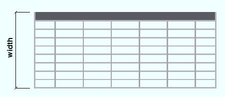
Tread width: The tread width , including the nosing plate width (in the primary dimension " Units " or in other units ).
Grade: The steel grades that may be shown here come from the Grating Grades setup window at Home > Project Settings > Job . Since connection design does not reference the steel grade applied to a grating tread, there are no Fy and Fu values on that setup window. The " Steel Grade " of a grating tread may be made to appear in a stair member's bill of material.
Grating Tread Material window: Grating grade .
Nosing width: The width of the nosing plate (in the primary dimensioning " Units ").

page 1 | contents | home > project settings > fabricator > | classic | top
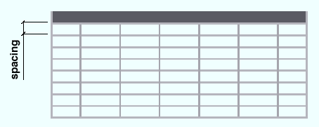
Quantity: The total number ( count ) of bearing bars.
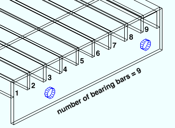
Spacing: The center-to-center distance (in the primary dimension " Units " or in other units ) between one bearing bar to the next.
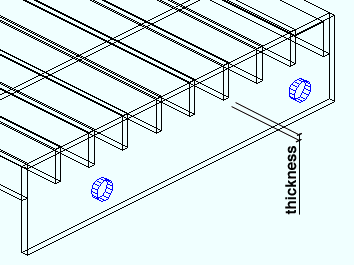
Thickness: The thickness (in the primary dimension " Units " or in other units ) of any one bearing bar. All bearing bars will be this same thickness.
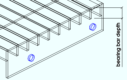
Depth: The depth (in the primary dimensioning " Units ") of any one bearing bar. All bearing bars will be this same depth.
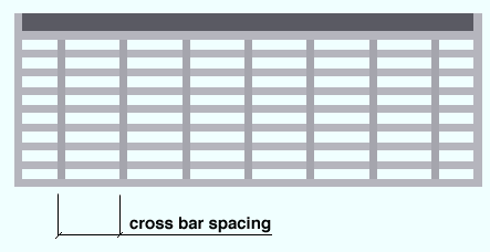
Spacing: The center-to-center distance (in the primary dimension " Units " or in other units ) from any one cross bar to the next cross bar.
Thickness: The thickness (in the primary dimension " Units " or in other units ) of any one cross bar. All cross bars will be this same thickness.
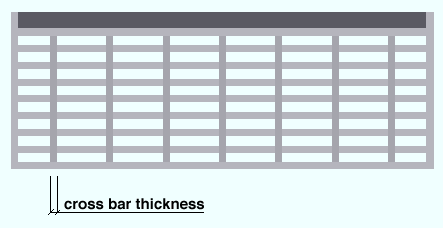
Depth: The height (in the primary dimension " Units " or in other units ) of each cross bar.
For tread that is level, this distance will be the difference between the elevation of the top of the cross bar and the bottom of that same cross bar. All cross bars will be the depth you specify here.
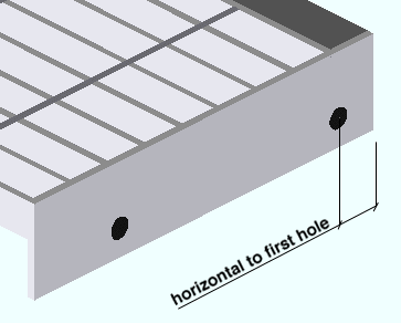
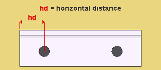
Horizontal distance: The horizontal distance (in the primary dimension " Units " or in other units ) from the end plate vertical edge nearest the nosing to the center of the nearest hole.
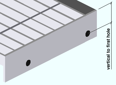
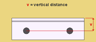
Vertical distance: The vertical distance (in the primary dimension " Units " or in other units ) from the horizontal edge of the end plate to the center of the hole nearest the nosing.
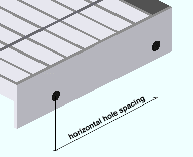
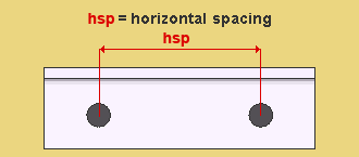
Horizontal spacing: The horizontal distance (in the primary dimension " Units " or in other units ) between the centers of adjacent holes. In the example shown, there are only 2 holes, but a full-featured SDS2 program will design the grating tread end plate using more holes if the " Tread width " is large enough for more holes to fit.
Bolt diameter: The diameter (in the primary dimension " Units " or in other units ) of the bolts that are to be inserted into the holes in the end plates.
Welded grating tread: To get grating stair tread without bolts and holes, type in a " Bolt diameter " of ' 0 '.
Bolt diameter sets the hole diameter: A full-featured SDS2 program automatically designs standard round holes in the end plate. The diameter of these holes are calculated from the " Bolt diameter " per the selected " Connection design method ." For AISC design codes, refer to Table J3.3 or Table J3.3M ( AISC Thirteenth Edition , p. 16.1-105).
Bolt type: A307 or A325N or A325SC or A325X or etc. The type of bolt to be used for fastening the tread to the stair stringers.
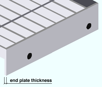
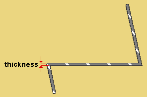
Thickness: The thickness of the end plate in the primary dimensioning " Units ".
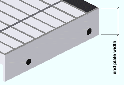
Depth: The depth of the end plate in the primary dimensioning " Units ."
Remarks (BOM): Any string (up to 23 characters) may be entered. The string of characters might, for example, be the name of the company from which the stair tread will be purchased, or the tread's part number. The characters entered here populate the " Remarks " column in the bill of material of any stair that uses this stair tread definition.
page 1 | contents | home > project settings > fabricator > | classic | top
Plate Stair Tread
Type of tread: Pan or Grating or Plate or Continuous .
For ' Pan ', see Bent Pan Stair Tread .
For ' Grating ', see Grating Stair Tread .
If ' Plate ' is selected, the following options apply.
For ' Continuous ', see Continuous Stair Tread .
Name: See " Name ."
Shape: C-shaped (up or down) or Cold formed channel or Other or Rolled channel or Rolled cold formed channel or Rolled cold formed z .
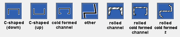
' C-shaped (up or down) ' give you " C-shaped " options. The tread points down in the model if ' C-shaped (down) ' is selected.
' Cold formed channel ' gives you " Cold formed channel " options.
' Other ' gives you " Other " options.
' Rolled channel ' gives you " Rolled channel " options.
' Rolled cold formed channel ' gives you " Rolled cold formed channel " options.
' Rolled cold formed z ' gives you " Rolled cold formed z " options.
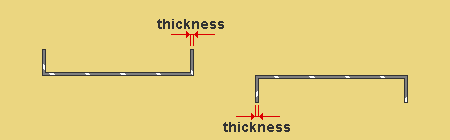
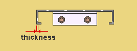
Plate thickness: The thickness (" Material thickness ") (in the primary dimension " Units " or other units ) of the bent plate layout material that is used to model the C-shaped treads.
Gage plate: If, for example, ' 4GA ' is entered here, then this is a gage plate. Allowable gages are any whole number from 3 to 38. The " Description " for a gage plate follows the format: ' plate type prefix ' + ' numberGA ' + ' x ' + ' width ' (example: PL16GAx15 1/2 ).
Grade: A36 or A572 or etc. The grade of steel for the bent plate layout material that is used to model the C-shaped treads.
Setup: Available steel grades for multi-bend plate material are defined at Home > Project Settings > Job > Plate Grades .
Checkered: ![]() or
or ![]() .
.
If this box is checked (
), this C-shaped plate tread is a checkered plate, which is a steel plate with raised ribs on its top horizontal surface to prevent slippage on the stair treads. The " Plate thickness " of a checkered plate is measured exclusive of the raised pattern. The prefix set for " Checkered " in Member and Material Piecemarking is applied to the " Description " on the General Information window and in the member bill of material ( example: PL3/8x10 becomes CHPL3/8x10 when ' CH ' is the prefix and it is set to " Append ... ." It becomes CH3/8x10 when not set to " Append... "). The " Weight of item " increases per AISC Table 1-23 ( Thirteenth Edition , p1-87) and also may depend on whether " Shop bill weight based on material " is set to ' Volume ' or ' Dimensions '. The plate will be detailed with a checkered pattern .
If the box is not checked (
), the C-shaped plate treads are considered to have smooth near-side surfaces.
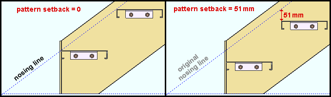
Pattern setback: The distance ( vertical ) (in the primary dimension " Units " or other units ) that the C-shaped plate treads are to be offset from the workline of the stair. A " Pattern setback " of ' 0 ' aligns the nosing line with the workline of the stair.
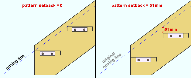
|
| In the right example, the " Pattern setback " is 51 mm (2 inches). |
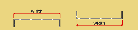
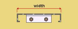
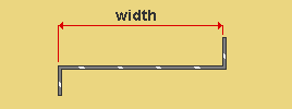
Tread width: The distance ( horizontal ) (in the primary dimension " Units " or other units ) between the two outside corners of the heel of the C-shaped tread. On a C-shaped stair tread that has been installed, this distance is measured horizontally.
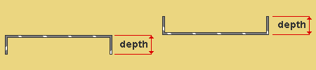
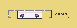
Depth: The distance ( vertical ) (in the primary dimension " Units " or other units ) from the heel of the C-shaped stair tread to the toe of either of the two legs. Both legs of a C-shaped tread are this same depth. On a C-shaped stair tread that has been installed, this distance is measured vertically.
----- Cold formed channel -----
Plate thickness: The thickness (" Material thickness ") (in the primary dimension " Units " or other units ) of the bent plate layout material that is used to model the cold-formed channel treads.
Gage plate: If, for example, ' 4GA ' is entered here, then this is a gage plate. Allowable gages are any whole number from 3 to 38. The " Description " for a gage plate follows the format: ' plate type prefix ' + ' numberGA ' + ' x ' + ' width ' (example: PL16GAx15 1/2 ).
Grade: A36 or A572 or etc. The grade of steel for the bent plate layout material that is used to model the cold-formed channel treads.
Setup: Available steel grades for multi-bend plate material are defined at Home > Project Settings > Job > Plate Grades .
Checkered: ![]() or
or ![]() .
.
If this box is checked (
If the box is not checked (
Pattern setback: The distance ( vertical ) (in the primary dimension " Units " or other units ) that the cold-formed channel treads are to be offset from the workline of the stair. A " Pattern setback " of ' 0 ' aligns the nosing line with the workline of the stair.
|
| In the right example, the " Pattern setback " is 51 mm (2 inches). |
Tread width: The distance ( horizontal ) (in the primary dimension " Units " or other units ) between the bends at the top of the cold-formed channel tread. .
Depth: The distance ( vertical ) (in the primary dimension " Units " or other units ) from the top of the tread to the bend in the leg (either leg) of the cold-formed channel tread.
Inside leg: The distance ( horizontal ) (in the primary dimension " Units " or other units ) from from the bottom bend in the vertical leg (either vertical leg) to the toe of the horizontal leg (either horizontal leg) of the cold-formed channel tread.
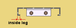
Plate thickness: The thickness (" Material thickness ") (in the primary dimension " Units " or other units ) of the bent plate layout material that is used to model the "other" type treads.
Gage plate: If, for example, ' 4GA ' is entered here, then this is a gage plate. Allowable gages are any whole number from 3 to 38. The " Description " for a gage plate follows the format: ' plate type prefix ' + ' numberGA ' + ' x ' + ' width ' (example: PL16GAx15 1/2 ).
Grade: A36 or A572 or etc. The grade of steel for the bent plate layout material that is used to model the "other" type treads.
Setup: Available steel grades for multi-bend plate material are defined at Home > Project Settings > Job > Plate Grades .
Checkered: ![]() or
or ![]() .
.
If this box is checked (
If the box is not checked (
Pattern setback: The distance ( vertical ) (in the primary dimension " Units " or other units ) that the "other" type treads are to be offset from the workline of the stair. A " Pattern setback " of ' 0 ' aligns the nosing line with the workline of the stair.
|
| In the right example, the " Pattern setback " is 51 mm (2 inches). |
Tread width: The distance ( horizontal ) (in the primary dimension " Units " or other units ) from the nosing corner of the tread to the inside face of the riser.
|
" Tread width " excludes the thickness of the riser leg. |
Nosing leg angle: The angle (in degrees) between the bottom of the tread and the inside face of the nosing leg. This angle must be 90 degrees or less (an acute angle).
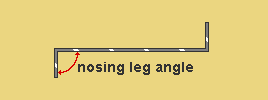
|
In this example, the " Nosing leg angle " is 90 degrees. |
Nosing leg: The distance ( actual ) (in the primary dimension " Units " or other units ) from the top of the tread to the bottom of the nosing leg.
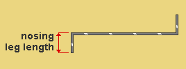
|
In this example, the " Nosing leg " length is measured vertically since the nosing leg is vertical. |
Riser leg: The distance ( actual ) (in the primary dimension " Units " or other units ) from the bottom of the tread to the top of the riser leg.
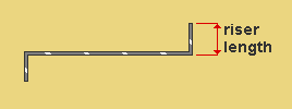
|
In this example, the " Riser leg " length is measured vertically since the riser leg is vertical. |
Riser leg angle: The angle (in degrees) between the top of the tread and the inside face of the riser leg. This angle must be 90 degrees or greater (an obtuse angle).
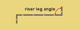
|
In this example, the " Riser leg angle " is 90 degrees. |
Section size: A section for a channel material (C or MC) that is listed in the local shape file .
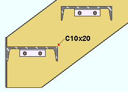
|
To generate this example of rolled channel stair treads, a " Section size " of ' C10x20 ' was entered. |
Grade: A36 or A572-42 or A588 or etc The grade of steel for the rolled section material that is used to model the rolled channel treads.
Setup: Available steel grades for channels come from Home > Project Settings > Job > Channel Grades .
----- Rolled cold formed channel -----
Section size: A section for a cold formed channel material that is listed in the local shape file .
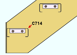
|
To generate this example of rolled cold formed channel stair treads, a " Section size " of ' C714 ' was entered. |
Grade: A992 or A572-42 or A36 or etc. The grade of steel for the rolled cold formed channel treads.
Setup: Available steel grades for rolled cold formed channel treads are defined at Home > Project Settings > Job > Wide Flange Grades .
----- Rolled cold formed z -----
Section size: A section for a cold formed z material that is listed in the local shape file .
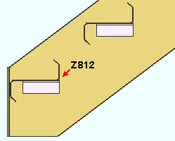
|
To generate this example of rolled cold formed z stair treads, a " Section size " of ' Z812 ' was entered. |
Grade: A992 or A572-42 or A36 or etc. The grade of steel for the rolled cold formed z treads.
Setup: Available steel grades for rolled cold formed z treads are defined at Home > Project Settings > Job > Wide Flange Grades .
----- Tread support ( for plate tread ) -----
Type: None or Single support . A tread support can be applied to any tread that can be defined when the " Type of tread " is ' Plate '.
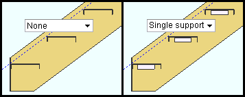
' None ' gives you stair treads without supports.
' Single support ' places supports (plate, flat bar or angle) under the stair treads. Settings on this window such as " Material description ," " Long leg to " and " Length " control various characteristics of the supports.
Material description: A plate description or flat bar description or angle section size .
A plate description is designated by the "Plate" prefix + thickness x width. For example, PL1/4x2, where PL is the plate prefix.
A flat bar description is designated by the "Flat bar" prefix + thickness x width. For example, FL1/4x2, where FL is the flat bar prefix.
An angle section size may be any section that is defined in the local shape file (e.g. L1x1x1/8).
Long leg to: Stringer or Tread . This applies when an angle with unequal legs has been entered as the " Material description ." If the legs of the angle are equal, the choice made here does not matter.
' Stringer ' designates at the long leg of the angle is the leg that bolts to the stringer. This leg will be the vertical leg when the tread and its support are installed.
' Tread ' designates that the long leg of the angle is the leg that supports the tread. This leg will be the horizontal leg when the tread and its support are installed.
Length: The distance ( horizontal ) that the support, when installed, will be flush to the bottom of the tread. The angle, flat bar or plate support will be cut to this length.
|
In this example, the support is an angle. The tread is a C-shaped plate. |
Setback: The distance ( horizontal ) from the nosing point to the support.
|
In this example, the support is an angle. The tread is a C-shaped plate. |
----- Holes (in plate tread support angles) -----
| Warning: The message " Holes are not on support material " indicates that a stair in the model that uses this tread definition will not have any holes in its tread support angles. The user of a full-featured SDS2 program needs to make changes on this window in order to get holes in the tread support angles. For example, that user may need to select a different angle (" Material description "), or the user may need to specify a different " Vertical distance ." |
Horizontal distance: The distance ( horizontal ) (in the primary dimension " Units " or other units ) from the corner of the support angle that is nearest the nosing point to the nearest hole in the angle.
|
Holes are placed in the support angle's leg to stringer (the vertical leg). |
Vertical distance: The distance ( vertical ) (in the primary dimension " Units " or other units ) from the top face of the horizontal leg of the angle (the leg to the tread) to the nearest hole in the leg to the stringer.
|
A " Vertical distance " that is too large may result in holes not being on the material. See the warning above. |
Horizontal spacing: The distance ( horizontal ) (in the primary dimension " Units " or other units ) from the center of one hole in the leg to the stringer to the center of the other hole in the leg to the stringer.
|
The " Horizontal spacing " in this example is the " Length " of the angle minus twice the " Horizontal distance ." |
Bolt diameter: The diameter (inches or mm) of the shank of the bolt. This sets the size of the two standard round holes that will be placed in the angle leg to the stringer (the vertical angle leg). It also sets the diameter of bolts that will be inserted into those holes.
| diameter |
|
' 0 ' results in no holes or bolts. 0 might be entered if the angles are to be welded to the stringers.
' 3/8 ' is the default bolt diameter.
Any bolt size -- including metric and imperial sizes -- may be entered.
Bolt type: A325 or A307 or etc.
Setup: Available bolt types are defined at Home > Project Settings > Job > Bolts, Washers, and Holes > Bolt Specifications .
Remarks (BOM): Any string (up to 23 characters) may be entered. The string of characters might, for example, be the name of the company from which the stair tread will be purchased, or the tread's part number. The characters entered here populate the " Remarks " column in the bill of material of any stair that uses this stair tread definition.
page 1 | contents | home > project settings > fabricator > | classic | top
Continuous Stair Tread
Type of tread: Pan or Grating or Plate or Continuous .
For ' Pan ', see Bent Pan Stair Tread .
For ' Grating ', see Grating Stair Tread .
For ' Plate ', see Plate Stair Tread .
If ' Continuous ' is selected, the following options become availalble.
Name: See " Name ."
----- Continuous tread settings -----
Plate thickness: The thickness (" Material thickness ") (in the primary dimension " Units " or other units ) of the bent plate layout material that is used to model the continuous stair treads.
Gage plate: If, for example, ' 4GA ' is entered here, then this is a gage plate. Allowable gages are any whole number from 3 to 38. The " Description " for a gage plate follows the format: ' plate type prefix ' + ' numberGA ' + ' x ' + ' width ' (example: PL16GAx15 1/2 ).
Grade: A36 or A572 or etc. The grade of steel for the bent plate layout material that is used to model the continuous stair treads.
Setup: Available steel grades for multi-bend plate material come from the Plate Grades setup window.
Checkered: ![]() or
or ![]() .
.
If this box is checked (
If the box is not checked (
Leg length: The distance ( actual ) (in the primary dimension " Units " or other units ) from the corner at the leg bend to the end of the leg.
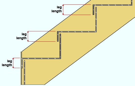
|
| In this example, the stair's " Bottom tread schedule " is set to ' Use Intermediate '. Consequently, the bottom tread leg length is the same as the leg length for the intermediate treads. |
Return top: The distance ( horizontal ) (in the primary dimension " Units " or other units ) from the top bend to the end of the top return. If ' 0 ' is entered, there will be no top return. .
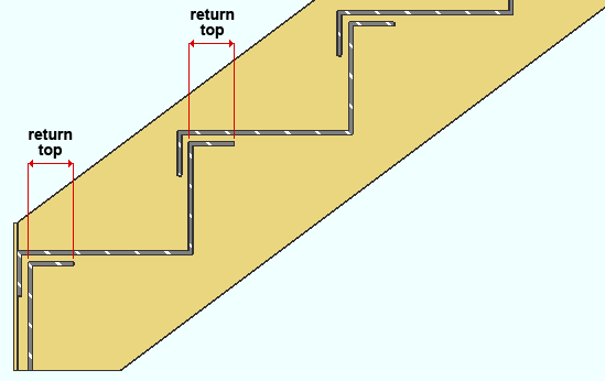
|
| In this example, the stair's " Bottom tread schedule " and " Intermediate tread schedule " are both set to use the same tread defintion. Consequently, the top return length is the same on each of the treads that are dimensioned. |
Return bottom: The distance ( horizontal ) (in the primary dimension " Units " or other units ) that the tread is extended. A " Return bottom " of ' 0 ' makes the riser perfectly vertical.
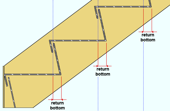
|
| In this example, the " Return bottom " is 51 mm (2 inches). if the " Return bottom " had been ' 0 ', the risers would be perfectly vertical and would align with the construction lines that are shown. |
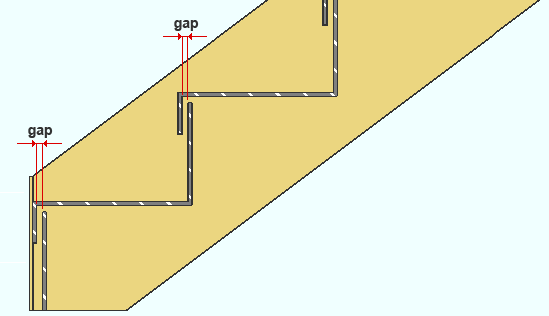
Gap: The distance ( actual ) (in the primary dimension " Units " or other units ) from the riser for one tread to the leg for the adjacent tread that is immediately above that tread.
Clearance: The distance ( actual ) (in the primary dimension " Units " or other units ) from the top of a riser to the bottom of the adjacent tread that is immediately above that riser.
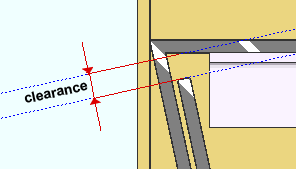
|
This clearance is measured paralllel with the riser. |
Pattern setback: The distance ( vertical ) (in the primary dimension " Units " or other units ) that the continuous stair treads are to be offset from the workline of the stair. A " Pattern setback " of ' 0 ' aligns the nosing line with the workline of the stair.
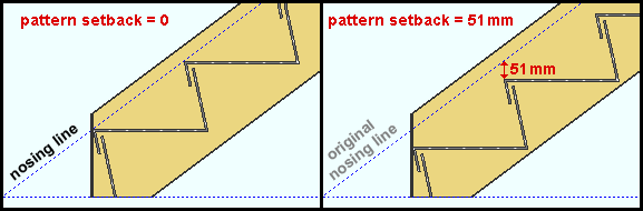
|
| In the right example, the " Pattern setback " is 51 mm (2 inches). |
----- Tread support (for continuous tread) -----
Type: None or Single support or Dual support .
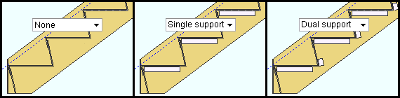
' None ' results in stair treads without supports.
' Single support ' places a tread support under the tread. The positioning and length of this support is calculated automatically and can be reviewed under " Tread support settings " on a Stair Review window in which this stair tread definition is specified. Users in a full-featured SDS2 program can adjust the length and positioning of the tread support. Other support dimensions are specified here, on this window, by entering a " Material description ."
' Dual support ' puts a tread support under the tread and a riser support on the riser. The positioning and length of these supports are calculated automatically and can be reviewed under " Tread support settings " on a Stair Review window in which this stair tread definition is specified. Users in a full-featured SDS2 program can adjust the length and positioning of the tread supports. Other support dimensions are specified here, on this window, by entering a " Material description ."
Material description: A plate description or flat bar description or angle description .
A plate description is designated by the "Plate" prefix + thickness x width. For example, PL1/4x2, where PL is the plate prefix.
A flat bar description is designated by the "Flat bar" prefix + thickness x width. For example, FL1/4x2, where FL is the flat bar prefix.
An angle description may be any section that is in the local shape file .
Long leg to: Stringer or Tread . This applies when an angle with unequal legs has been entered as the " Material description ." If the legs of the angle are equal, the choice made here does not matter.
Remarks (BOM): Any string (up to 23 characters) may be entered. The string of characters might, for example, be the name of the company from which the stair tread will be purchased, or the tread's part number. The characters entered here populate the " Remarks " column in the bill of material of any stair that uses this stair tread definition.
page 1 | contents | home > project settings > fabricator > | classic | top