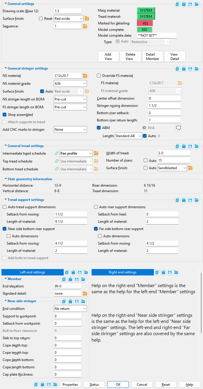
The Stair Review window ( Modeling ) (" Status " & " Properties " enabled )
To open this window :
- Member Review
- Review by Piecemark
- Review by Member Number
- Double-click on stringer in Select mode
- "Edit..." on context menu, select stair piecemark
- Search Options
Also see :
- Stair Treads (setup)
|
|||
|
|
|||
|
|
|||
|
|
|||
|
|
|||
|
|
||
|
|
|||
Drawing scale ( Base 12 or Base 10 ): The scale at which the 2D member detail of this stair will be drawn. The drawing scale shown here is the same as the " Drawing scale " on the Drawing Data window in the Drawing Editor .
( Base 12 ) means the scale is in ' Imperial ' units. 1.5 inch equals one foot is the default scale if you are using imperial units.
( Base 12 ) means the scale is in ' Metric ' units.
Surface Finish :None or Sandblasted or Red oxide or Yellow zinc or Gray oxide or Blued steel or Galvanized or Duplex Coating or Undefined 1 or Undefined 2 or Undefined 3 or Red oxide 2 or Any user added surface finish. This affects the colors of 'Solid ' members on erection views in the Drawing Editor . This also sets the color when "Output material color " is set to 'Surface finish ' for a VRML Export or a DWG/DXF Export . The "Color " ( not "Surface finish ") sets the color of this material in Modeling .
| sand blasted | red oxide | yellow zinc | user surface finish 1 |
| gray oxide | blued steel | galvanized | user surface finish 2 |
To assign a different surface finish, you can drop-down the current surface finish and select the one you want, or you can press the "file cabinet" browse button (
) and double-click any surface finish that is on the list.
Reset ![]() or
or ![]() .
.
If this box is checked (
), all attached materials' surface finish are reset to follow what is selected on the member level, general stringer settings, or general tread settings. If the general stringer settings or general tread settings has the auto check box (
If the box is not checked (
), all attached materials' surface finish remains at what is set inside the material edit window.
Note: Stringer and Tread Surface finishes can be controlled separately if the auto check box is unchecked. The stringer and tread materials follow what is set inside of the general stringer settings and general tread settings. If either of these have the auto check box checked, it will follow what is set in the General settings.
------------------
Main material : ![]() or
or ![]() .
.
Marked for detailing : ![]() or
or ![]() .
.
Model complete : ![]() or
or ![]() .
.
Model complete date : **NOT SET** or a month day year .
page 1 | contents | review | top
|
|
|||
|
|||
|
|
|||
|
|
|||
|
|
|||
|
|
||
|
|
|||
NS material: The section size of the near-side stringer and, by default, the far-side stringer. Allowable materials for stringers are channel (C) or tube steel (TS) or plate (e.g., ' PL3/8x14 '). Users of a full-featured SDS2 program can optionally override the choice made here for the far-side stringer.
NS material grade: A grade of steel ( A36 or A441 or etc.) from the setup list for HSS/TS Grades (for tube stringers) or the list for Channel Grades (for channel stringers) or the list for Plate Grades (for plate stringers).
Surface finish: None or Sandblasted or Red oxide or Yellow zinc or Gray oxide or Blued steel or Galvanized or Duplex Coating or Undefined 1 or Undefined 2 or Undefined 3 or Red oxide 2 or Any user added surface finish. This affects the colors of 'Solid ' members on erection views in the Drawing Editor . This also sets the color when "Output material color " is set to 'Surface finish ' for a VRML Export or a DWG/DXF Export . The "Color " ( not "Surface finish ") sets the color of this material in Modeling .
| sand blasted | red oxide | yellow zinc | user surface finish 1 |
| gray oxide | blued steel | galvanized | user surface finish 2 |
To assign a different surface finish, you can drop-down the current surface finish and select the one you want, or you can press the "file cabinet" browse button (
Auto ![]() or
or ![]() .
.
If this box is checked (
If the box is not checked (
NS stringer length on BOM: Pre-cut or Post-cut . This " ![]() General stringer settings " option applies when the " End condition " for the NS stringer is ' Bolt to floor '. The default for this option the " New stair stringer length on BOM " in setup.
General stringer settings " option applies when the " End condition " for the NS stringer is ' Bolt to floor '. The default for this option the " New stair stringer length on BOM " in setup.
Example: A short stair with a bolt-to-floor end condition.
Pre-cut Post-cut 

' Pre-cut ' results in the " Length " reported for the near side stringer in this stair's bill of material being the " Order length " of that material. This also corresponds to what is referred to as the saw length on the CNC Setup window. This is the length of the stringer material before cuts were made to its end so that it could be bolted to the floor.
' Post-cut ' results in the stringer's " Length " in the bill being its " Part length ." For CNC, this is referred to as the final length. This is the length of the stringer material after its end was cut so that it could be bolted to the floor.
FS stringer length on BOM: Same as the " NS stringer length on BOM ," except that this applies to the far-side stringer.
If this box is checked (
If the box is not checked (
Attach supports to tread: ![]() or
or ![]() . This "
. This " ![]() General stringer settings " option applies when "
General stringer settings " option applies when " ![]() Shop assembled " is not checked.
Shop assembled " is not checked.
|
| These examples show a continuous tread with angle supports. |
If this box is checked (
If the box is not checked (
If this box is checked (
If the box is not checked (
FS material: The section size of the far-side stringer. By default, the choice made here automatically matches the choice made to " NS material ." The default may be overridden if " ![]() Override FS material " is checked.
Override FS material " is checked.
FS material grade: A36 or A441 or etc. By default, the choice made here automatically matches the choice made to " NS material grade ." The default may be overridden if " ![]() Override FS material " is checked.
Override FS material " is checked.
Center offset dimension: The positive or negative (-) distance (in the primary dimension " Units " or in other units ) that the center of the stair is offset from its workline.
' 0 ' (zero) means the stair is centered around its workline.
A ' positive distance ' means the stair is offset toward the near side of its workline.
A ' negative (-) distance ' means the stair is offset toward the far side of its workline.
Stringer nosing dimension: The distance (in the primary dimension " Units " or in other units ) between the top flange of the stringer and the workline (the workline runs along the tops of the risers). This distance is measured perpendicular to the workline.
Bottom riser setback: A positive or negative (-) distance ( vertical ) (in the primary dimension " Units " or other units ). This " ![]() General stringer settings " option applies when the " Bottom tread schedule " is a continuous tread . It also applies when the " Intermediate tread schedule " is for pan treads .
General stringer settings " option applies when the " Bottom tread schedule " is a continuous tread . It also applies when the " Intermediate tread schedule " is for pan treads .
' 0 ' (zero) results in the bottom riser not being set back. The bottom riser's vertical dimension will be the same as the vertical dimension of the other risers in the stair.
' A positive distance ' extends the vertical dimension of the bottom riser downward, toward the floor. As a result, the bottom riser's vertical dimension will be larger than the vertical dimension of the other risers.
' A negative distance ' sets back the riser from the floor. As a result, the bottom riser's vertical dimension will be smaller than the vertical dimension of the other risers.
Bottom riser return length: A positive or negative (-) distance ( horizontal ) (in the primary dimension " Units " or other units ). This " ![]() General stringer settings " option applies when the " Bottom tread schedule " is a continuous tread . It also applies when the " Intermediate tread schedule " is for pan treads .
General stringer settings " option applies when the " Bottom tread schedule " is a continuous tread . It also applies when the " Intermediate tread schedule " is for pan treads .
' 0 ' (zero) results in no return.
' A positive distance ' results in a return of the length that is entered. The return will be inward, toward the opposite end of the stair.
' A negative distance ' results in a return of the length that is entered. The return will be outward, away from the stair.
Add CNC marks to stringers: None or Nosing or Support . A CNC mark is a hole with a diameter of 0. This " ![]() General stringer settings " option lets the user of a full-featured SDS2 program instruct that program to automatically add CNC marks to the inside faces of stair stringers to facilitate proper alignment of treads or tread supports.
General stringer settings " option lets the user of a full-featured SDS2 program instruct that program to automatically add CNC marks to the inside faces of stair stringers to facilitate proper alignment of treads or tread supports.
|
| This example shows pan treads with dual angle supports. CNC marks can be applied to other types of treads and other support configurations as well. |
' None ' puts no CNC marks on the inside of the stair stringers.
' Nosing ' puts one CNC mark per stringer for each tread nosing. The CNC marks are placed on the inside of each stringer. This applies regardless of the " Type of tread " (pan or grating or plate or continuous). On pan treads, the CNC marks align with the " Abrasive setback ."
' Support ' puts two CNC marks per angle or plate or flat bar support in line with the corners of the support where the tread or riser rests on the support. The CNC marks are placed on the inside of both the NS and FS stringers since each stringer will have a support. If the support is a bent plate, a single CNC mark is placed at the intersection of the riser with the next tread near the bend location.
page 1 | contents | review | top
|
|
|||
|
|
|||
|
|||
|
|
|||
|
|
|||
|
|
||
|
|
|||
Intermediate tread schedule: The " Name " of the stair tread definition that is to be used for intermediate treads in this stair. Sixteen distinct stair tread definitions can be defined in Home > Project Settings > Fabricator > Stair Treads . Any one definition may include specifications for pan treads or grating treads or plate treads or continuous treads .
|
A stair can have many intermediate treads. It can have only one top tread and one bottom tread. |
indicates that the " Intermediate tread schedule " that is selected here is still linked to the tread definition with that same " Name " at Home > Project Settings > Fabricator Stair Treads . Consequently, if the user of a full-featured SDS2 program were to change that tread definition in setup, this intermediate tread would update in the model.
indicates that the " Intermediate tread schedule " that is selected here no longer links to the tread definition with that same " Name " at Home > Project Settings > Fabricator > Stair Treads .
indicates mixed linked-unlinked status, which applies when you are simultaneously reviewing multiple stairs on this same window.
Top tread schedule: Use intermediate or a number . This " ![]() General tread settings " option applies when the choice made to " Intermediate tread schedule " is a stair tread definition for grating treads or plate treads or continuous treads .
General tread settings " option applies when the choice made to " Intermediate tread schedule " is a stair tread definition for grating treads or plate treads or continuous treads .
|
|
The top tread is the highest tread on a stair. |
' Use intermediate ' specifies that the top tread use the same stair tread definition as the " Intermediate tread schedule ."
' A number ' corresponding to a stair tread definition applies that definition to the top tread.
Bottom tread schedule: Use intermediate or a number . This " ![]() General tread settings " option applies when the choice made to " Intermediate tread schedule " is a stair tread definition for grating treads or plate treads or continuous treads .
General tread settings " option applies when the choice made to " Intermediate tread schedule " is a stair tread definition for grating treads or plate treads or continuous treads .
|
|
The bottom tread is the lowest tread on a stair. |
' Use intermediate ' specifies that the bottom tread use the same stair tread definition as the " Intermediate tread schedule ."
' A number ' corresponding to a stair tread definition applies that definition to the bottom tread.
Width of tread: The width of the tread in the appropriate distance " Units ." The maximum width that may be shown here is ' 180 ' inches (' 4572 ' mm).
Number of risers: The count ( 1 or 2 or 3 or ...) of risers
|
The count can be calculated automatically (" |
Layout considerations: A stair is automatically laid out so that the tops of the risers are along the workline that was input when the stair was added. For a given stair, increasing the number of risers increases the number of steps and causes each step to be smaller.
Surface finish: None or Sandblasted or Red oxide or Yellow zinc or Gray oxide or Blued steel or Galvanized or Duplex Coating or Undefined 1 or Undefined 2 or Undefined 3 or Red oxide 2 or Any user added surface finish. This affects the colors of 'Solid ' members on erection views in the Drawing Editor . This also sets the color when "Output material color " is set to 'Surface finish ' for a VRML Export or a DWG/DXF Export . The "Color " ( not "Surface finish ") sets the color of this material in Modeling .
| sand blasted | red oxide | yellow zinc | user surface finish 1 |
| gray oxide | blued steel | galvanized | user surface finish 2 |
To assign a different surface finish, you can drop-down the current surface finish and select the one you want, or you can press the "file cabinet" browse button (
Auto ![]() or
or ![]() .
.
If this box is checked (
If the box is not checked (
page 1 | contents | review | top
|
|
|||
|
|
|||
|
|
|||
|
|||
|
|
|||
|
|
||
|
|
|||
Horizontal distance: The horizontal distance (in the primary dimension " Units " or in other units ) between the work points of this stair.
Vertical distance: The vertical distance (in the primary dimension " Units " or in other units ) between the two work points of this stair. This " ![]() Stair geometry information " distance is the difference between the Z global axis coordinates (elevation) of those work points.
Stair geometry information " distance is the difference between the Z global axis coordinates (elevation) of those work points.
Riser dimension: A vertical distance (in the primary dimension " Units " or in other units ) that directly relates to the " Number of risers " that is entered.
Tread dimension: A horizontal distance (in the primary dimension " Units " or in other units ) that directly relates to the " Number of risers " that is entered.
page 1 | contents | review | top
|
|
|||
|
|
|||
|
|
|||
|
|
|||
|
|||
|
|
||
|
|
|||
| Not all stairs have " Tread support settings ." These settings are available when the selected " Intermediate tread schedule " is a continuous tread type or pan tread type and the support " Type " (in the Stair Treads ) is ' Single support ' or ' Dual supports '. |
Auto tread support dimensions: ![]() or
or ![]() . This "
. This " ![]() Tread support settings " option applies to stair tread definitions using continuous treads or pan treads with ' Dual supports ' or a ' Single support '. The choice made to " Intermediate tread schedule " on this window (the Stair Review window) sets the stair tread definition. The supports specified in a definition can be an angle, plate or flat bar " Material description ."
Tread support settings " option applies to stair tread definitions using continuous treads or pan treads with ' Dual supports ' or a ' Single support '. The choice made to " Intermediate tread schedule " on this window (the Stair Review window) sets the stair tread definition. The supports specified in a definition can be an angle, plate or flat bar " Material description ."
If this box is checked (
If the box is not checked (
Setback from nosing: The distance ( horizontal ) (in the primary dimension " Units " or other units ) from the stair tread's nosing point to the tread support.
|
The tread nosing points in this example of continuous treads are at intersections of construction lines . This setback can also be applied to pan treads . |
Length of material: The length ( horizontal ) (in the primary dimension " Units " or other units ) of the near-side and far-side tread supports. These tread supports can be angles, plates or flat bars.
|
Angle tread supports are shown in this example. The width and thickness dimensions of the angle (or plate or flat bar) are based on the " Material description " that is entered to Fabricator > Stair Treads for continuous treads or pan treads . |
Auto riser support dimensions : ![]() or
or ![]() . This "
. This " ![]() Tread support settings " option applies to stair tread definitions using continuous treads or pan treads with ' Dual supports '.
Tread support settings " option applies to stair tread definitions using continuous treads or pan treads with ' Dual supports '.
If this box is checked (
If the box is not checked (
Setback from heel: The distance ( actual ) (in the primary dimension " Units " or other units ) from the heel of the tread to the riser support. This distance is measured parallel with the riser.
|
This setback is measured parallel with the riser. In this example of a continuous tread , the riser happens to be vertical. |
Length of material: The length ( actual ) (in the primary dimension " Units " or other units ) of the riser support material (angle, plate, flat bar). The length of a riser support, once it has been installed, is its dimension parallel with the riser. In the example below, the risers are vertical; therefore, the length of a riser support would be the vertical dimension of that support.
|
The riser material in this example is an angle. The " Length of material " can also be specified when the riser material is a plate or flat bar. |
Near side bottom riser support: ![]() or
or ![]() . This "
. This " ![]() Tread support settings " option applies to stair tread definitions using continuous tread or pan treads with ' Dual supports ' or a ' Single support '. Such a tread definition must have been applied, for a continuous tread, to the " Bottom tread schedule ." For a pan tread, the definition must have been applied to the " Intermediate tread schedule ."
Tread support settings " option applies to stair tread definitions using continuous tread or pan treads with ' Dual supports ' or a ' Single support '. Such a tread definition must have been applied, for a continuous tread, to the " Bottom tread schedule ." For a pan tread, the definition must have been applied to the " Intermediate tread schedule ."
|
| This view was created using Snap to Farside and clicking on the near-side stringer. It shows the far side of the near-side stringer. |
If this box is checked (
If the box is not checked (
Auto dimensions:
If this box is checked (
If the box is not checked (
Setback from nosing: The distance ( actual ) from the first nosing point to the support material. This distance is measured parallel with the riser. If "
This setback is measured parallel with the riser. The riser shown for the continuous tread in this example happens to be vertical. Length of material: The distance ( actual ) between the top and bottom edges of the far-side riser support material. If "
The other dimensions of the angle, plate or flat bar -- its width and thickness -- are based on the " Material description " that is entered at Home > Project Settings > Fabricator > Stair Treads .
Far side bottom riser support: ![]() or
or ![]() . This "
. This " ![]() Tread support settings " option applies to stair tread definitions using continuous tread or pan treads with ' Dual supports ' or a ' Single support '. Such a tread definition must be applied, for a continuous tread, to the " Bottom tread schedule ." For a pan tread, the definition must have been applied to the " Intermediate tread schedule ."
Tread support settings " option applies to stair tread definitions using continuous tread or pan treads with ' Dual supports ' or a ' Single support '. Such a tread definition must be applied, for a continuous tread, to the " Bottom tread schedule ." For a pan tread, the definition must have been applied to the " Intermediate tread schedule ."
|
| This view was created using Snap to Farside on the far-side stringer. It shows the far side of the far-side stringer. |
If this box is checked (
If the box is not checked (
Auto dimensions:
If this box is checked (
If the box is not checked (
Setback from nosing:
|
This setback is measured parallel with the riser. The riser shown for the continuous tread in this example happens to be vertical. |
Length of material:
The support shown here is an angle, but it could instead be a plate or flat bar. The support material type is the " Material description " that is entered in Home > Project Settings > Fabricator > Stair Treads ." The other dimensions of the angle, plate or flat bar -- its width and thickness -- are based on that material description.
Add bolts to tread support: ![]() or
or ![]() .. This "
.. This " ![]() Tread support settings " option applies to stairs using continuous treads or pan treads with ' Single supports ' that are angle material.
Tread support settings " option applies to stairs using continuous treads or pan treads with ' Single supports ' that are angle material.
If this box is checked (
If the box is not checked (
Edge distance: The distance (in the primary dimension " Units " or other units ) from the left vertical edge of the tread support angle to the nearest hole for bolting the angle to the stringer. " Edge distance " is always a horizontal dimension since tread support angles are always modeled as horizontal. The " Edge distance " applies when " ![]() Add bolts to tread support " is checked.
Add bolts to tread support " is checked.
|
ed = edge distance. Note that this distance is measured from the left edge of the vertical leg. |
Spacing: The distance (in the primary dimension " Units " or other units ) from the center of one hole in the tread support angle to the center of the other hole in the angle. A tread support angle has two holes, both in the leg that bolts to the stringer. " Spacing " is always a horizontal dimension since tread support angles are always modeled as horizontal. The " Spacing " applies when " ![]() Add bolts to tread support " is checked.
Add bolts to tread support " is checked.
|
|
The tread that is supported by the angle is not shown in this example of the inside of a stair stringer. |
In a full-featured SDS2 program . . .
'
'
Gage: The distance (measured vertically in the primary dimension " Units " or other units ) from the heel of the horizontal leg of the angle that supports the tread to either hole in the vertical leg of the angle, which bolts to the stringer. This dimension is the same for each of the two holes and is always a vertical dimension. The " Gage " applies when " ![]() Add bolts to tread support " is checked.
Add bolts to tread support " is checked.
|
|
The tread that is supported by the angle is not shown in this example of the inside of a stair stringer. |
In a full-featured SDS2 program . . .
'
'
Bolt type: A325 or A307 or etc. This " ![]() Tread support settings " option sets the type of bolt to be used for fastening the vertical leg of the angle support to the stringer. The " Bolt type " applies when "
Tread support settings " option sets the type of bolt to be used for fastening the vertical leg of the angle support to the stringer. The " Bolt type " applies when " ![]() Add bolts to tread support " is checked.
Add bolts to tread support " is checked.
Bolt diameter: The diameter (inches or mm) of the shank of the bolt. This " ![]() Tread support settings " option also sets the size of the two standard round holes that will be placed in the angle leg to the stringer (the vertical angle leg). The " Bolt diameter " applies when "
Tread support settings " option also sets the size of the two standard round holes that will be placed in the angle leg to the stringer (the vertical angle leg). The " Bolt diameter " applies when " ![]() Add bolts to tread support " is checked.
Add bolts to tread support " is checked.
| diameter |
|
page 1 | contents | review | top
|
|
|||||||
|
|
|||||||
|
|
|||||||
|
|
|||||||
|
|
|||||||
|
|
|||||||
|
|
||||||
End elevation: The elevation (in the primary dimension " Units " or in other units ) of the work point of this stair. An " End elevation " must be specified for both the left end and the right end work point.
|
The Stair Review window has separate " End elevation " fields under its Left End Settings and Right End Settings banners. |
Standard Detail: None or the name of a job standard detail or global standard detail . A "Standard detail " may be entered for the left end and/or the right end of the stair.
If ' none ' is entered here, then no standard detail will be applied on the end of the stair when it is automatically detailed in a full-featured SDS2 program .
If a ' standard detail name ' is entered here, next time the auto detailing of this stair takes place in a full-featured SDS2 program , the reference point of the standard detail will align with the input work point on the end of the stair, and the standard detail's bill of material will be combined with the stair's bill of material. The detail is placed on a layer that is named after the standard detail plus a "_L" or "_R" suffix.
page 1 | contents | review | top
|
|
|||||||
|
|
|||||||
|
|
|||||||
|
|
|||||||
|
|
|||||||
|
|
|||||||
|
|
||||||
End condition: No return or Return or Bolt to floor or Top cap . This is the required end condition for this stringer. An " End condition " needs to be specified for both the left- and the right-end NS stringers and for both the left- and the right-end FS stringers.
' No return ' cuts the stair stringer vertically, in alignment with the stair workpoint when " Support to workpoint " and " Setback from workpoint " are zero.
' Return ' adds a horizontal return, the length of which is based on the " Support to workpoint " distance.
' Bolt to floor ' cuts the bottom end of the stair stringer so that it is horizontal and can, for example, lay flat on a floor. A " Bolt to floor clearance " may be entered. For the top end, horizontal an vertical cuts are made to the stringer so that the top tread can be laid on the floor.
' Top cap ' cuts the top of the stringer flat and adds a top cap plate that is the " Cap plate thickness ." The plate may be extended based on the " Support to workpoint ."
Support to workpoint: The distance (in the primary dimension " Units " or in other units ) from the supporting material (the end of the return) to the work point of the stringer at this end. This dimension sets the length of the specified return. A " Support to workpoint " needs to be specified for both the left- and the right-end NS stringers and for both the left- and the right-end FS stringers.
Setback from workpoint: The positive or negative (-) distance ( horizontal ) (in the primary dimension " Units " or other units ) that the " Support to workpoint " is set back from the support. This distance, together with the " Support to workpoint ," sets the length of the return. A " Setback from workpoint " can be specified for both the left- and the right-end NS stringers and for both the left- and the right-end FS stringers when a " Support to workpoint " distance has been entered.
|
Both the " Support to workpoint " and the " Setback from workpoint " are dimensioned on the member detail. |
A positive distance makes the return shorter.
A negative distance makes the return longer.
Bolt to floor clearance: The distance ( vertical ) (in the primary dimension " Units " or other units ) that the stair is set back from its work point. This applies when the " End condition " is set to ' Bolt to floor '.
Slab to top return: The vertical distance (in the primary dimension " Units " or in other units ) between the top of the slab and the top of the return steel. A " Slab to top return " distance needs to be specified for both the left- and the right-end NS stringers and for both the left- and the right-end FS stringers.
Cope depth top: The depth (in the primary dimension " Units " or in other units ) of the L-shaped cut at the top of the return. This distance is measured parallel with the depth of the return material. A " Cope depth top " distance needs to be specified for both the left- and the right-end NS stringers and for both the left- and the right-end FS stringers.
Cope length top: The length (in the primary dimension " Units " or in other units ) of the L-shaped cut at the top of the return. This distance is measured parallel with the length of the return material. A " Cope length top " distance needs to be specified for both the left- and the right-end NS stringers and for both the left- and the right-end FS stringers.
Cope depth bottom: The cope depth (in the primary dimension " Units " or in other units ) required at the bottom of the return. A " Cope depth bottom " distance needs to be specified for both the left- and the right-end NS stringers and for both the left- and the right-end FS stringers.
Cope length bottom: The cope length (in the primary dimension " Units " or other units ) required at the bottom of the return. A " Cope length bottom " distance needs to be specified for both the left- and the right-end NS stringers and for both the left- and the right-end FS stringers.
Cap plate thickness: The thickness (in the primary dimension " Units " or other units ) of the cap plate or, if applicable, the top cap. A thickness of ' 0 ' (zero) results in no cap plate or top cap.
|
A cap plate can be applied to the top end or bottom end of a stringer when the" End condition " is ' Return ' or ' No return ' or ' Bolt to floor '. " Cap plate thickness " sets the plate's thickness. |
|
A top cap can be applied to the top end of a stringer when the " End condition " is ' Top cap '. The " Cap plate thickness " sets the plate's thickness. |
page 1 | contents | review | top
|
|
|||||||
|
|
|||||||
|
|
|||||||
|
|
|||||||
|
|
|||||||
|
|
||||||
|
|
||||||
Graphical: Indicates a course of action taken in a full-featured SDS2 program .
"
"
Supporting member: a member number . At this time, the supporting member must be a beam in order for the stair to properly connect to it. However, users of a full-featured SDS2 program can still get a connection even if their is no supporting member or the supporting member is, for example, a column. Zero (0) indicates no supporting member.
Connection type: Plain end or Clip angle or Shear or Floor clip .
| Click here for documentation on stair connections from the SDS2 Detailing help manual. Users can edit such connections in the SDS2 Detailing program. Users can only review stair connections in SDS2 Site Planning. |
|
|
|
' Plain end ' is the default connection type. It gives no connection.
' Clip angle ' can give the user of a full-featured SDS2 program a connection when the " End condition " is ' No return ' or ' Return '.
' Shear ' can give the user of a full-featured SDS2 program a connection when the " End condition " is ' No return ' or ' Return '.
' Floor clip ' can give the user of a full-featured SDS2 program a connection when the " End condition " is ' Bolt to floor '.
page 1 | contents | review | top
"Properties" opens the Edit Properties window, on which you can make entries to custom properties . If, at the time it was created, your current Job was set to use a legacy flavor, the window that opens is named Custom Properties , not Edit Properties .
The Edit Properties window can also be used to read "
Log " entries or review or type "
Tip: Model > Member > Properties is an alternative to this button. It opens the Edit Properties window directly, without your first having to open a member review window.
" Status " opens the Member Status Review window for the stair(s) that you are reviewing. You can use that window to update status information about the stair(s).
" OK " (or the Enter key) closes the Stair Review window (this window) and saves to the member file(s) any changes made on the Member Status Review window.
Change all: If you double-clicked a stair and made a change to its status and the 3D model contains other members with the same piecemark as this stair, a yes-no dialog opens after you press " OK ." On that yes-no dialog is the question, " Do you want to change all .... " Press the " Yes " button to update the status of all the stairs with this piecemark; press the " No " button to change only this one stair.
" Cancel " (or the Esc key) closes this window without saving any status changes made on the Member Status Review window.
" Reset " undoes all status changes you made to this member on the Member Status Review window.