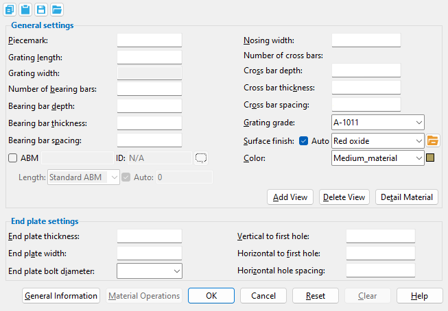
The Grating Tread Material window ( Modeling ) (read-only)
Also see :
- General Information window (can be opened from this window)
- Submaterial piecemark (each unique material identified by)
- Submaterial detail (2D drawing of a material)
- Add bearing bar thickness to grating tread description ( Member Detailing Settings )
page 1 | contents | material review | material types | top
------ General settings ------
Piecemark: The submaterial piecemark ( up to 61 characters ) for the grating tread whose settings you are reviewing.
Note: Grating tread system piecemarks begin with the material mark prefix for " Grating tread. " For the quantity of grating treads that have been assigned this piecemark, refer to the " Current quantity " listed on this material's General Information window.
Grating length: The length (in the primary dimension " Units " or in other units ) of the grating tread along its longitudinal axis ( X material axis ).
Note: This distance directly relates to the " Number of cross bars ," but does not affect their thickness and spacing.
Grating width: The distance (in the primary dimension " Units " or in other units ) of the grating tread along its Y material axis .
Note: Grating width is calculated based on the following formula: grating tread width = [( number of bearing bars - 1)( bearing bar spacing )] + bearing bar thickness + nosing width .
Number of bearing bars: The total number ( 1 or 2 or 3 or ...) of bars that are parallel with the grating tread's X material axis .
Bearing bar depth: The distance (in the primary dimension " Units " or in other units ) between the top and bottom edges of any one bearing bar. All bearing bars will be this same depth.
Bearing bar thickness: The thickness (in the primary dimension " Units " or in other units ) of any one bearing bar. All bearing bars will be this same thickness.
Fabricator Setup: Add bearing bar thickness to grating tread description ( Member Detailing Settings )
Bearing bar spacing: The spacing (in the primary dimension " Units " or in other units ) between any one bearing bar and the next bearing bar plus the thickness of the one bearing bar.
Nosing width: The width (in the primary dimension " Units " or in other units ) of the nosing plate. This dimension is measured from the workline edge of the grating tread to the nearest edge of the nearest bearing bar.
Number of cross bars: The number of bars (1 or 2 or 3 or ...) that are parallel with the grating tread's Y material axis , not including the end plates.
Cross bar depth: The distance (in the primary dimension " Units " or in other units ) between the top and bottom edges of any one cross bar. In other words, this is the Z material axis dimension of the cross bar. All cross bars will be the depth you specify here.
Example: For grating tread laid out in a plan view, this distance will be the difference between the elevation of the top of the cross bar and the bottom of that same cross bar.
Cross bar thickness: The thickness (in the primary dimension " Units " or in other units ) of any one cross bar. All cross bars will be this same thickness.
Cross bar spacing: The spacing (in the primary dimension " Units " or in other units ) between any one cross bar cross bar and the next cross bar plus the thickness of the one cross bar.
Grating grade: Any steel grade from the Grating Grades setup window at Home > Project Settings > Job may have been assigned to the grating tread that you are reviewing.
Note: For a grating tread that is part of a stair member, the grade shown here may have been assigned not on this window, but by specifying it as the " Grade " on the Stair Tread Defintion Schedule .
Surface finish: None or Sandblasted or Red oxide or Yellow zinc or Gray oxide or Blued steel or Galvanized or Duplex Coating or Undefined 1 or Undefined 2 or Undefined 3 or Red oxide 2 or Any user added surface finish. This affects the colors of 'Solid ' members on erection views in the Drawing Editor . This also sets the color when "Output material color " is set to 'Surface finish ' for a VRML Export or a DWG/DXF Export . The "Color " ( not "Surface finish ") sets the color of this material in Modeling .
| sand blasted | red oxide | yellow zinc | user surface finish 1 |
| gray oxide | blued steel | galvanized | user surface finish 2 |
To assign a different surface finish, you can drop-down the current surface finish and select the one you want, or you can press the "file cabinet" browse button (
) and double-click any surface finish that is on the list.
Auto ![]() or
or ![]() .
.
If this box is checked (
), the material surface finish follows what is set on the member level.
If the box is not checked (
), the material surface finish can be changed to whatever is available in the list of surface finishes. If the surface finish changes from what the member level has set, the auto checkbox will be unchecked automatically. When the auto check box is unchecked, the member edit window shows an information tag which notifies the user that an attached material is not following what was set on the member level.
Note 1: Submaterial piecemarks can be split apart by surface finish. All surface finishes that do not have the 'Break Marks Material' checked on can be applied to any like material with out the material splitting. If the 'Break Marks Material' is checked on then only like materials with that specific surface finish can have the same piecemark, and because the submaterial marks differ so would the member's piecemark.
Note 2:When exporting a KISS file using "model" as the "Data source " surface finish data on the materials are compiled into the KISS download as follows, with a few exceptions (G=galvanized, N= none or sandblasted, P= others). Those exceptions are:
If the box for "Finish" routing in KISS export setup is set to a user routing
If the user has adjusted the Abbreviation for any of the default provided surface finishes
If you are using a user added surface finish
In these cases you will get what is provided in either the User routing, or the abbreviation field. For other exports it will always provide the abbreviation in the 'surface finishes' settings page.
Tip 1: "Surface area" is reported on the General Information window -- and this can be used to estimate the amount of coating required and its cost.
Tip 2: Changing "Steel grade " "Color " and "Surface finish " do not cause the plate to be regenerated. This means that, if you change those settings only, material fit operations such as a Fit Exact may, optionally, be preserved.
Report Writer:MemberMaterial.Material.SurfaceFinish
Setup:Surface Finish Settings
Color: The color of the grating tread when it is displayed in solids form . Different colors may be assigned to materials that have the same submaterial piecemark . The color swatch next to the list box ( ![]() ) displays the color that is selected.
) displays the color that is selected.
Setup: The default colors for member main materials and submaterials is set up on the Modeling Colors setup window.
page 1 | contents | material review | material types | top
End plate thickness: The thickness (in the primary dimension " Units " or in other units ) of the grating tread's end plates.
End plate width: The distance (in the primary dimension " Units " or in other units ) from the workline to the bottom edge of the end plate.
End plate bolt diameter: The diameter of bolt used in the end plates of this grating tread.
Note: Standard round holes are used in the end plate. The diameter of these holes is calculated from the " End plate bolt diameter ." For an AISC connection design method, this calculation is done per Table J3.3 or Table J3.3M ( AISC Thirteenth Edition , p. 16.1-105).
Vertical to first hole: The vertical distance (in the primary dimension " Units " or in other units ) from the top edge of the end plate to the center of the first hole.
Horizontal to first hole: The horizontal distance (in the primary dimension " Units " or in other units ) from the nosing edge of the end plate to the first hole.
Horizontal hole spacing: The horizontal distance (in the primary dimension " Units " or in other units ) from the center of one hole to the center of the next hole.
Note: This distance also determines the number of holes on the end plate. If grating width - (2)( horizontal to first hole ) > (2)(horizontal hole spacing), three holes are used (or more holes if there is enough space). If grating width - (2)( horizontal to first hole ) > (3)(horizontal hole spacing), four holes are used (or more holes if there is enough space).
page 1 | contents | material review | material types | top
To close this window :
![]()
![]()
" General Information " opens the General Information window, which you can use to review additional information about the selected material.
Press " Close " on the General Information window to close that window and reactivate this window.
"OK" (or the Enter key) closes this window.
page 1 | contents | material review | material types | top