Stair Connection Edit
- General Overview
- Tips and Tricks
- Related Tools
Connection Type
Graphical: ![]() or
or ![]() . This stair connection is automatically marked as "
. This stair connection is automatically marked as " ![]() Graphical " whenever you make graphical changes to any of its materials, bolts or welds by, for example, adding a hole to a connection material, performing a cut or fit operation on a connection material, or editing or deleting a material, bolt or weld. In other words, graphical changes are changes that are made to a connection outside of this window or the Stair Edit window.
Graphical " whenever you make graphical changes to any of its materials, bolts or welds by, for example, adding a hole to a connection material, performing a cut or fit operation on a connection material, or editing or deleting a material, bolt or weld. In other words, graphical changes are changes that are made to a connection outside of this window or the Stair Edit window.
If this box is checked (
), changes you make on this window -- for example, to the " Attachment " of the connection -- will not be applied in the model since the member is prevented from undergoing Process and Create Solids .
If the box is not checked (
), any graphical changes made to this stair connection will be lost the next time the stair undergoes Create Solids . Also, any entries made on this window will be applied to the stair connection at that time. If User and Site Options > Modeling > " Automatically process after modeling operation " is set to ' Process and create solids ', then this connection will automatically be regenerated ( Create Solids will take place) after your press " OK ."
Supporting member number: 0 or a member number [ num ].
|
The supporting member must be a beam. That beam needs to be perpendicular to the stair. You can get connections when there is no supporting member. But welds or bolts will not automatically be added when there is no member or a member that is not a beam. |
' 0 ' indicates that there is no supporting beam for the stair connection to connect to. When ' 0 ' is the " Supporting member number ," you will not get a connection when you have specified that the angle or shear plate be shop welded to the supporting member. Nevertheless, you will get a connection for other situations where there is no supporting member. That connection will not be able to bolt to a supporting member, however, since there is no supporting beam.
A ' number greater than 0 ' is the member number [num] of the member that the connection connects to.
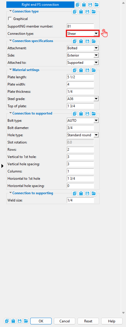
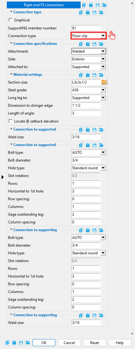
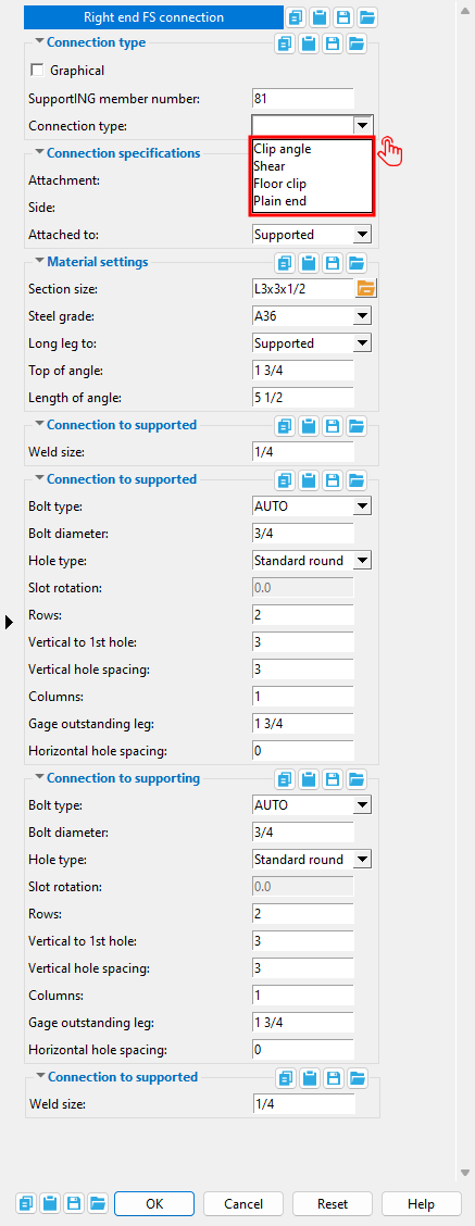
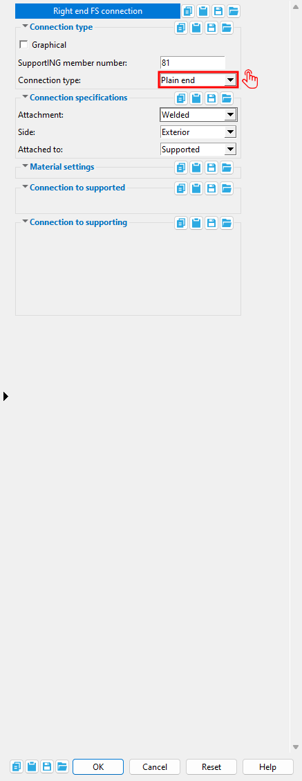
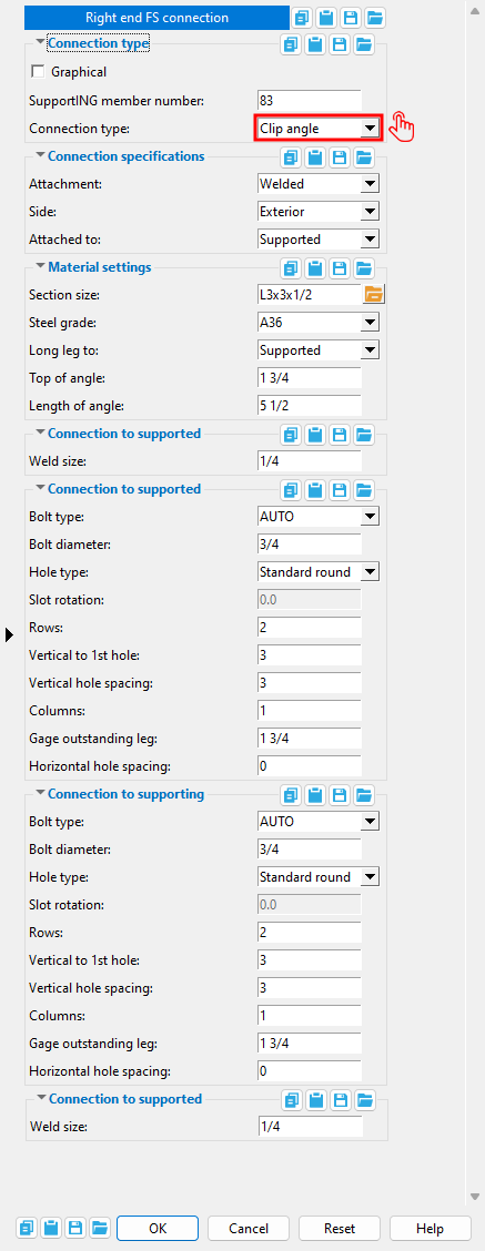
Connection type: See " Connection type " on the Stair Edit window. The choice you make here updates the choice made on that window. The location noted in the banner at the top of this window tells you which section to look under on the Stair Edit window. The following banners may appear at the top of the Stair Connection edit window.
| Left end NS connection |
| Right end NS connection |
| Left end FS connection |
| Right end FS connection |
Connection Specifications
Attachment: Bolted or Welded . The method of shop attachment to the " Attached to " member.
|
| Four distinct configurations can be specified when the " Connection type " is ' Clip angle '. A supporting member (beam) is required when the "Attachment" is ' Welded ' and " Attached to " is ' Supporting '. |
|
| Making choices to " Attachment " and " Attached to " can create two distinct shear plate connections. A shear plate always welds to the beam and bolts to the stair. Which member the shear plate shop attaches to can be varied. |
|
| When the " Connection type " is ' Floor clip ' and a supporting member (beam) supports the bottom of the stair, four distinct clip angle configurations can be configured using " Attachment " and " Attached to ." |
' Bolted ' specifies that the connection be shop bolted to the " Attached to " member.
' Welded ' specifies that the connection be shop welded to the " Attached to " member. Note in shear plate example shown above that ' Welded ' and ' Supported ' does not weld the shear plate to the stair.
Side: Interior or Exterior . This applies when ' Clip angle ' or ' Shear ' or ' Floor clip ' is the " Connection type ."
|
This example shows clip angle connections at the ends of stair returns. Shear plate connections and floor clip connections can also be set to be attached to the ' Interior ' or the ' Exterior ' of a stair stringer or return. |
' Interior ' puts the connection on the inside of the stringer (or return).
' Exterior ' puts the connection on the outside of the stringer (or return).
Attached to: Supporting or Supported . In each of the following illustrations, the supporting member is the beam, and the supported member is the stair.
|
|
| " Attachment " together with " Attached to " can be used to configure four distinct clip angle configurations. |
|
|
| " Attachment " together with " Attached to " can be used to configure two distinct shear plate configurations. |
|
|
| " Attachment " together with " Attached to " can be used to configure four distinct floor clip configurations. |
' Supported ' specifies that the " Attachment " choice be used as the method for shop attaching the connection to the stair.
' Supporting ' specifies that the " Attachment " choice be used as the method for shop attaching the connection to the beam. If ' Supporting ' is selected when there is no supporting member, the connection will not be generated when the model is processed.
Material Settings
Section size: Any section size for angle material that is in the local shape file . You can type in the section size that you want, or you can press the "file cabinet" browse button ( ![]() ) and double-click any section that is on the list of available materials in the local shape file. Validation only lets you enter a material that is listed in the local shape file. Also, if you enter a section size that is not available, validation brings up a yes-no dialog with the warning, " The section size is not available from suppliers. Are you sure you want to use it? "
) and double-click any section that is on the list of available materials in the local shape file. Validation only lets you enter a material that is listed in the local shape file. Also, if you enter a section size that is not available, validation brings up a yes-no dialog with the warning, " The section size is not available from suppliers. Are you sure you want to use it? "
Material Type Typing in a size Material Window angle naming convention " Section size " This applies to clip angle connections and to floor clip connections.
Steel grade: A36 or A572 or etc. The steel grade of the connection material. For a clip angle or floor clip connection, the connection material is angle material. For a shear plate connection, the connection material is rectangular plate material. If the grade of steel that you want is not shown as a menu option ( ![]() ), you can add the grade you want to the menu by entering it to the appropriate setup table.
), you can add the grade you want to the menu by entering it to the appropriate setup table.
| Stair
Connection |
Connection
Material |
Setup Table |
Material
Window |
| clip angle | angle | Angle Grades | " Steel grade " |
| floor clip | rectangular plate | Plate Grades | " Steel grade " |
Long leg to: Supported or Supporting . This applies to clip angle connections and floor clip connections when the " Section size " is an angle with unequal legs.
' Supported ' attaches the long leg of the angle to the stair.
' Supporting ' attaches the long leg of the angle to the beam (if there is a supporting member ).
Top of angle: The distance from the top of the return to the top of the angle. On a stair with no return, this distance is measured from the top corner of the stair stringer to the top of the angle. " Top of angle " is an option for stair clip angle connections.
|
The top of angle to top of stringer dimension is labeled top in this example of a clip angle connection. |
Dimension to stringer edge: The distance, horizontal from the vertical edge of the stringer to the vertical edge of the floor clip. This applies when the stair's " End condition " is ' Bolt to floor ' and the " Connection type " is ' Floor clip '.
|
The dimension to stringer edge is labeled e in this example of a floor clip connection. |
Length of angle: The distance between the outside edges of the angle whose " Section size " is specified above. In other words, this is the length which that angle will be cut to. For clip angle connections on stairs, this is a vertical dimension. For stair floor clip connections, this is a horizontal dimension.
|
|
The length of the angle is labeled len in this example of a clip angle connection. On a stair, a clip angle connection's length runs vertically. |
|
|
The length of angle is labeled len in this example of a floor clip connection. A floor clip's length runs horizontally. |
Locate @ setback elevation : ![]() or
or ![]() . This applies to floor clip connections.
. This applies to floor clip connections.
If this box is checked (
If the box is not checked (
Note: The " Bolt to floor clearance " is a stringer setting, which means that the left stringer and right stringer can each have a different " Bolt to floor clearance ."
Plate length: The distance from the top edge of the shear plate to its bottom edge. Plate length on a stair's shear plate connection is a vertical dimension.
|
The plate length is labeled len in this example of a shear plate connection. The length runs vertically. If you adjust the number of " Rows " or " Vertical hole spacing " (vsp), you may also need to adjust the " Plate length ." The program does not automatically make this adjustment for you. |
Plate width: The distance from the vertical framing edge of the shear plate to its vertical interior edge. Plate width on a stair's shear plate connection is a horizontal dimension.
|
|
The plate width is labeled width in this example of a shear plate connection. The width runs horizontally. This means that if you adjust the number of " Columns " or " Horizontal hole spacing " (hsp), you probably also want to adjust the " Plate width ." |
Plate thickness: The plate thickness of the shear plate.
|
Warning: Do not change this plate's " Material thickness " on the Rectangular Plate Material window. Do it here or on the Stair Edit window. Changing settings on a material window makes the stair's shear plate connection graphical . |
To enter gage plate: Type in the ' gage number' followed by ' ga ' (example: ' 4ga ' is rewritten as ' 4GA ' when you Tab out of the field). Right-click tells you the stored thickness (based on industry standards), from which the weight of the gage plate is calculated. Allowable gages are any whole number from 3 to 38 . You can also enter an exact decimal thickness to get the gage (example: ' .1345 ' becomes ' 10GA ' when you Tab out of the field). The " Description " for a gage plate follows the format: ' plate prefix ' + ' numberGA ' + ' x ' + ' width ' (example: PL16GAx15 1/2 ).
Top of plate: The distance from the top of the return to the top of the shear plate. On a stair with no return, this distance is measured from the top corner of the stair stringer to the top of the plate. " Top of plate " is an option for stair shear plate connections only.
|
|
The top of plate is labeled top in this example of a shear plate connection. |
Connection to supported ( to the stair )
Weld size: A distance that indicates depth of preparation of the fillet shop weld that attaches the stair connection to the stair. This sets the " Weld size " on the Weld Edit window in Modeling as well as the " Weld size " for the weld symbol on the stair detail.
Which stair connections can be welded to the supported? " Weld size " can apply to a clip angle or floor clip connection. You cannot weld a shear plate to the stair. The stair connection's " Attachment " must be set to ' Welded ' and " Attached to " must be set to ' Supported ' in order for you to get a shop weld to the stair.
Bolt type: AUTO or A307 or etc. This can apply to a stair's clip angle or floor clip connection (if the connection bolts to the stair stringer). This always applies to a stair's shear plate connection since such a connection always bolts to the stringer.
' AUTO ' applies the default " Bolt type " for non-moment connections that has been entered at Home > Project Settings > Job > Bolt Settings .
' Other bolt types ' that you can select on the menu (
) are originally defined in the Bolt Specifications .
Shop or field? The connection bolts are shop bolts or field bolts depending on the choices made to " Attachment " and " Attached to ."
Note: Since stair connections do not undergo connection design , the program does not check to see if the " Bolt type " or the " Bolt diameter " that you enter will stand up to loading conditions. It is your responsibility to ensure that the required design calculations are made.
Also see: The choice made here is the " Bolt type " of the bolt on its edit window. Do not change that " Bolt type " on its edit window as doing so will make this connection graphical .
Bolt diameter: The diameter (inches or mm) of the shank of the bolt. This is also the " Diameter " of the bolt on its edit window.
| diameter |
|
The hole in the connection that the bolt is inserted through is sized based on the bolt's " Diameter " and the " Hole type ."
Hole type: Standard round or Short slot or Oversized round or Long slot . This can apply to clip angle and floor clip connections (if they bolt to the stair). This always applies to a stair's shear plate connection since such a connection always bolts to the stair.

See Table J3.3 or Table J3.3M ( AISC Thirteenth Edition , p. 16.1-105) for information on how holes of particular types are sized with respect to the input " Bolt diameter ."
Slot rotation: A positive or negative value from 90 to -90 degrees. This is also the " Slot rotation " of the hole on its edit window. You can apply a slot rotation only when the " Hole type " is ' Long slot ' or ' Short slot '. Slot rotations can be modeled to a precision of 0.1 degree.
|
' 0 ' (zero) degrees makes the slot horizontal.
A ' positive number ' of degrees rotates the slot clockwise or counterclockwise depending on your perspective in the model.
A ' negative number ' of degrees rotates the slot in the opposite direction that a positive number rotates it.
Which material gets the slot? The slot whose rotation you specify here is in the connection material (clip angle, leg to supported or floor angle, leg to supported or shear plate). The matching hole in the stair stringer or stair return is a standard round hole, not a slot.
Rows: The number (a count) of rows of holes in the leg of a stair's clip angle connection or floor clip that bolts to the stringer (the supported). This also applies to shear plates, which always bolt to the stringer. Rows of holes to the supported run horizontally in each of these three connection interfaces.
|
|
The rows are labeled rows in this example of a clip angle connection that bolts to the supported stair. The number of rows in this example is 2. |
|
|
The rows are labeled rows in this example of a shear plate connection. Rows run parallel with the " Plate length " (len). |
|
|
The rows are labeled rows in this example of a floor clip connection that bolts to the supported stair. Since rows run parallel with the length of the stair, you may need to manually adjust the " Length of angle " when you change the number of rows. |
Vertical to 1st hole: The distance, vertical from the top of the stringer (or return) to the center of the top hole (or row of holes) in the leg of the clip angle that bolts to the stair. This also applies to shear plates, which always bolt to the stair.
|
|
The vertical to 1st hole dimension is labeled vert to 1st in this example of a clip angle connection that bolts to the supported stair. |
|
|
The vertical to 1st hole dimension is labeled vert to 1st in this example of a shear plate connection. |
Vertical hole spacing: The center-to-center distance between adjacent rows of holes in the clip angle or shear plate. Since rows of holes run horizontally in these types of stair connections, " Vertical hole spacing " is a vertical dimension.
|
|
The vertical hole spacing is labeled vspc in this example of a clip angle connection that bolts to the supported stair. |
|
|
The vertical hole spacing is labeled vsp in this example of a shear plate connection. |
Horizontal to 1st hole: The distance, horizontal from the vertical stringer edge to the center of the nearest hole in the leg of the floor clip connection that bolts to the stringer. The stringer edge is the vertical edge at the end of a stringer when the stair's " End condition " is ' Bolt to floor '.
|
|
The horizontal to 1st hole dimension is labeled 1st in this example of a floor clip connection that bolts to the supported stair. |
Row spacing: The center-to-center distance between adjacent rows of holes in the leg of the floor clip that bolts to the stair. Since rows of holes run horizontally in the leg to supported of a stair's floor clip connection, " Row spacing " is a vertical dimension.
|
|
The row spacing is labeled rsp in this example of a floor clip connection that bolts to the supported stair. |
Columns: The number (a count) of columns of holes in the leg of a stair's clip angle connection or floor clip that bolts to the stringer (the supported). This also applies to shear plates, which always bolt to the stringer. Columns of holes run vertically in each of these three connection interfaces.
|
|
The columns are labeled columns in this example of a clip angle connection that bolts to the supported stair. |
|
|
The columns are labeled columns in this example of a shear plate connection. |
|
|
The columns are labeled cols in this example of a floor clip connection that bolts to the supported stair. |
Gage outstanding leg: The distance from the heel of the angle to the nearest column (or row) of holes in the leg to the supported stair. This applies to clip angle connections and floor clip connections. For a clip angle connection, this is the horizontal dimension to the nearest column of holes. For a floor clip, this is the vertical dimension to the nearest row of holes.
|
|
The gage is labeled gol in this example of a clip angle connection that bolts to the supported stair. |
|
|
The gage is labeled gol in this example of a floor clip connection to the supported stair. |
Horizontal hole spacing: The center-to-center distance between adjacent columns of holes in the stair's clip angle or shear plate connection. Since columns of holes run vertically in these types of stair connections, " Horizontal hole spacing " is a horizontal dimension.
|
|
The horizontal hole spacing is labeled hspc in this example of a clip angle connection with dimensions for the leg to the supported stair. |
|
|
The horizontal hole spacing is labeled hsp in this example of a shear plate connection. |
Column spacing: The center-to-center distance between adjacent columns of holes in the leg of the floor clip that bolts to the stair. Since columns of holes run vertically in the leg to supported of a stair's floor clip connection, " Column spacing " is a horizontal dimension.
|
|
The column spacing is labeled csp in this example of a floor clip connection to the supported stair. |
Connection to supporting ( the beam )
Weld size: A distance that indicates the depth of preparation of the fillet weld that attaches the stair connection to the supporting member. This sets the " Weld size " on the Weld Edit window in Modeling as well as the " Weld size " for the weld symbol on the stair detail.
Connection types: This " Weld size " can apply to the leg to supporting member on a stair's clip angle or floor clip connection. It also applies to a shear plate connection, which always welds to the supporting member.
Shop weld to the supporting: The stair connection's " Attachment " can be set to ' Welded ' and " Attached to " can be set to ' Supporting ' in order for you to get a shop weld to the supporting beam.
Field weld to the supporting: For a shear plate connection, you can set the " Attachment " to ' Welded ' and " Attached to " to ' Supported ' in order to get a field weld to the supporting beam.
Bolt type: AUTO or A307 or etc. This can apply to a stair's clip angle or floor clip connection if the connection bolts to the supporting member. To get bolts in the model, the supporting member must be a beam.
' AUTO ' applies the default " Bolt type " for non-moment connections that has been entered at Home > Project Settings > Job > Bolt Settings .
' Other bolt types ' that you can select on the menu (
Shop or field? The connection bolts are shop bolts or field bolts depending on the choices made to " Attachment " and " Attached to ."
Note: Since stair connections do not undergo connection design , the program does not check to see if the " Bolt type " or the " Bolt diameter " that you enter will stand up to loading conditions. It is your responsibility to ensure that the required design calculations are made.
Also see: The choice made here is the " Bolt type " of the bolt on its edit window. Do not change that " Bolt type " on its edit window as doing so will make this connection graphical .
Bolt diameter: The diameter (inches or mm) of the shank of the bolt. This is also the " Diameter " of the bolt on its edit window.
| diameter |
|
The hole in the connection that the bolt is inserted through is sized based on the bolt's " Diameter " and the " Hole type ."
Hole type: Standard round or Short slot or Oversized round or Long slot . This can apply to a stair's clip angle or floor clip connection if it is set to be bolted to the supporting member -- see " Attachment " and " Attached to ."
See Table J3.3 or Table J3.3M ( AISC Thirteenth Edition , p. 16.1-105) for information on how holes of particular types are sized with respect to the input " Bolt diameter ."
Note: Even if no bolts are generated in the model due to there not being a supporting beam, holes will still be generated in the angle leg to supporting based on this " Hole type " and the above-entered " Bolt diameter ."
Slot rotation: A positive or negative value from 90 to -90 degrees. This is also the " Slot rotation " of the hole on its edit window. You can apply a slot rotation only when the " Hole type " is ' Long slot ' or ' Short slot '. Slot rotations can be modeled to a precision of 0.1 degree.
|
' 0 ' (zero) degrees makes the slot horizontal.
A ' positive number ' of degrees rotates the slot clockwise or counterclockwise depending on your perspective in the model.
A ' negative number ' of degrees rotates the slot in the opposite direction that a positive number rotates it.
Which material gets the slot? The slot whose rotation you specify here is in the angle leg to the supporting (floor clip or clip angle).The matching hole in the beam is a standard round hole, not a slot.
Rows: The number (a count) of rows of holes in the leg of a stair's clip angle connection or floor clip that bolts to the supporting member. Even if no bolts are generated in the model due to there not being a supporting beam, this number of rows of holes will still be generated in the leg to supporting.
|
The rows are labeled rows in this example of a clip angle connection that is bolted to the supporting beam's web. The number of rows in this example is 2. |
|
The rows are labeled rows in this example of a floor clip connection that is bolted to the supporting beam beam's top flange. The number of rows in this example is 2. |
Vertical to 1st hole: The distance, vertical from the top of the stringer (or return) to the first hole in the leg of the clip angle that is set to be bolted to the supporting member.
|
|
The vertical to 1st hole dimension is labeled vert to 1st in this example of a clip angle connection that is bolted to the supporting beam's web. |
Vertical hole spacing: The center-to-center distance between adjacent rows of holes in the leg of the clip angle that bolts to the supporting member. Since rows of holes run horizontally in these types of stair connections, " Vertical hole spacing " is a vertical dimension.
|
|
The vertical hole spacing is labeled vspc in this example of a clip angle connection that is bolted to the supporting beam's web. |
Horizontal to 1st hole: The distance measured horizontally from the vertical stringer edge to the center of the nearest hole in the leg of the floor clip connection that bolts to the supporting member. The stringer edge is the vertical edge at the end of a stringer when the stair's " End condition " is ' Bolt to floor '.
|
|
The horizontal to 1st hole dimension is labeled horz in this example of a floor clip connection that is bolted to the supporting beam's top flange. |
Row spacing: The center-to-center distance between adjacent rows of holes in the leg of the stair's floor clip connection that bolts to the supporting member. To get bolts in the model, that supporting member must be a beam
|
|
The row spacing dimension is labeled rsp in this example of a floor clip connection that is bolted to the supporting beam's top flange. |
Columns: The number (a count) of columns of holes in the leg of a stair's clip angle connection or floor clip that bolts to the supporting member.
|
|
The columns are labeled cols in this example of a clip angle connection for bolting to the supporting beam's web. The number of columns in this example is 2. |
|
|
The columns are labeled cols in this example of a floor clip connection that is bolted to the supporting beam's top flange. |
Gage outstanding leg: The distance, horizontal from the heel of the angle to the nearest column (or row) of holes in the leg to the supporting member of a stair's clip angle connection or floor clip connection. To get bolts in the model, that supporting member needs to be a beam -- see " Supporting member number ."
|
|
The gage on the outstanding leg is labeled gol in this example of a clip angle connection that is bolted to the supporting beam's web.. |
|
|
The gage on the outstanding leg is labeled ga in this example of a floor clip connection that is bolted to the supporting beam's top flange. |
Horizontal hole spacing: The center-to-center distance between adjacent columns of holes in the leg of the stair's clip angle connection that bolts to the supporting member. Since columns of holes run vertically in this type of stair connection, " Horizontal hole spacing " is a horizontal dimension.
|
|
The horizontal hole spacing is labeled hspc in this example of a clip angle connection with dimensions for the leg to the supporting beam. |
Column spacing: The center-to-center distance between adjacent columns of holes in the leg of the stair's floor clip connection that bolts to the supporting member.
|
|
The column spacing is labeled csp in this example of a floor clip connection that is bolted to the supporting beam's top flange. |
![]() Copy, Paste, Save, Load buttons:
Copy, Paste, Save, Load buttons:
- The position of these "form" buttons on the window tells you what settings they apply to. Click here for more information.
- You can
 Copy the settings on this window, then
  Paste those settings to a different edit window of the same type.
- You can
 Save the settings on this window to a file stored in a global folder that is used by your current version of SDS2. Give the file a name that will help other users identify its purpose. You can
  Load a saved file to replace the settings on this window (except Piecemark) with the settings that are stored in the file you select.
- When editing multiple windows at the same time, Paste and Load replace mixed entries to a single field with a single entry. Copy and Save ignore fields with mixed entries, treating them as if they have no entry or do not exist.
" OK " (or the Enter key) closes the edit window and saves any changes you have made on the window to the member file.
" Cancel " (or the Esc key or the ![]() button) closes the edit window without saving any changes that you have made.
button) closes the edit window without saving any changes that you have made.
" Reset " undoes any changes made since you opened this window.
- Add Stair (placing a stair in the 3D model)
- Stair Edit (double-click a stair to open)
- Stair Quick Add Tool (another way to add a stair) (
 )
)
- Cut Stair and Handrail Detailing Time in Half (YouTube) ( )
- Stair Treads ( Home > Project Settings > Fabricator > )
- Member attributes for stairs (for parametric modification)