 Stair Quick Add Tool ( Modeling )
Tool summary:
- Lets you add multiple flights of stairs in a single operation. Each flight is a single stair member.
- To open the Stair Edit window to edit a stair member, double-click any part of a stair.
- Setup for the Stair Quick Add Tool can be done at Home > Project Settings > Job > Plugin Defaults > Commands > Stair Quick Add Tool .
- The icon can be taken from the group named ' Model -- Parametric ' and placed on the ribbon. Stair Quick Add can also be configured to be invoked using a keyboard shortcut , the context menu , or a mode . For the lightning interface, this configuration is done using Customize Interface.
- Along with the videos described below, see Cut Stair and Handrail Detailing Time in Half (
 ) (YouTube).
Also see:
- Stair Quick Add Setup (Job Setup)
- Stair Edit window (edits stairs added with the Stair Quick Add tool)
- Add Stair (another tool to add stairs)
Videos:
|
|
|
|
|
The Quick Stair Add window for elevation views:
The Quick Stair Add - Plan View window:
The Quick Stair Add - Flight Settings window:
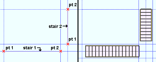
Step-by-step instructions (plan views):
The following instructions assume that you are using a 3-button mouse while in an plan view with grid lines or construction lines already laid out. Also, be sure to define the stair tread you want to apply to this stair at Home > Project Settings > Fabricator > Stair Treads if you have not already done so.
You will add at least one workline that designates the positioning of the tops of the risers of a stair (the nosing line):
The width of the stair tread is centered along the same work line that positions the tops of the risers of the stair.
Adding these four points, for example, adds two worklines that create "L" shaped stairs.
1. Invoke Add Stair by clicking the Quick Stair Add Tool icon.
2 .Locate - Pan - Return mouse bindings become active.
|
|
|
bindings |
2a : Select an appropriate Locate option, position the mouse pointer (
) so that the point location target (
) snaps to where you want the low end of the workline of the stair. Left-click ( Locate ).
2b : The status line prompts, "Select second point:" Reposition the point location target (
3. The Quick Stair Add - Plan View window opens.
3a: Enter a "Tread" and a "Riser" height. Also, be sure to select the stair tread that you want from the " Tread schedule " menu.
3b: If you are adding multiple stairs (step 6) that will be connected by landings, be sure that "Use previous elevation" is checked (
). You can also have the program
3c: When you are done entering stair settings, press the "OK" button.
4. The Quick Stair Add - Flight Settings window opens. Confirm the "First point...," "Second point elevation," and other settings, the press the "OK" button.
5. (optional) Repeat steps 2 and 3 to add additional stairs.
6. Right-click (Return) to end the operation. The stair or stairs are generated on screen in solids form and are automatically assigned piecemarks.
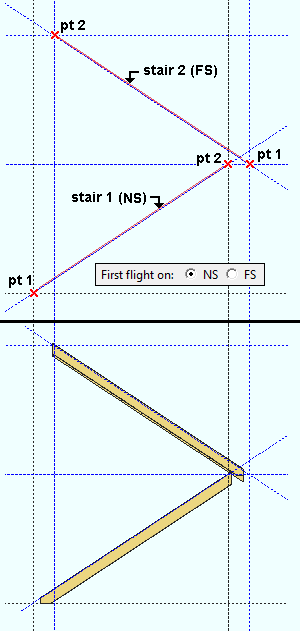
Step-by-step instructions (elevation views):
The following instructions assume that you are using a 3-button mouse while in an elevation view with grid lines or construction lines already laid out. Also, define the stair tread you want to apply to this stair at Home > Project Settings > Fabricator > Stair Treads if you have not already done so.
You will add at least one workline that designates the positioning of the tops of the risers of a stair (the nosing line):
The width of the stair tread is offset from the same work line that positions the tops of the risers of the stair by entries to "NS..." and "FS Flight offset"
Adding these four points, for example, creates "switchback" stairs:
1. Invoke Add Stair by clicking the Quick Stair Add Tool icon.
2 .Locate - Pan - Return mouse bindings become active.
|
|
|
bindings |
2a: Select an appropriate Locate option, position the mouse pointer (
2b: The status line prompts, "Select second point:" Reposition the point location target (
3. The Quick Stair Add window opens.
3a:Choose to locate the "First flight on" either 'NS' or 'FS', and set an "NS..." or "FS Flight offset" as appropriate. This chooses the side for the first stair that you add.
3b: Be sure to select the stair tread that you want from the " Tread schedule " menu.
3c: Enter other settings as appropriate. When you are done entering stair settings, press the "OK" button.
4. (optional) Repeat step 2 to add additional stairs. If "First flight on" was set to 'NS', the next stair you add will be a far side stair, the stair after that will be a near side stair, etc.
5. Right-click (Return) to end the operation. The stair or stairs are generated on screen in solids form and are automatically assigned piecemarks.
Quick Stair Add window settings (all views):
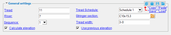
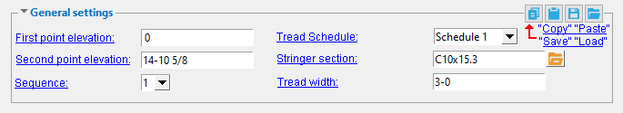
Tread Schedule: The "Name" of the stair tread definition that you want used for treads in this stair. Setup for 16 distinct stair tread definitions can be configured in Home > Project Settings > Fabricator > Stair Treads.
Stair Edit window: "Intermediate tread schedule"
Tread width: The width of the tread (horizontal) (in the primary dimension "Units" or other units ) The maximum value accepted by validation on the Stair Edit window is '180 ' inches ('4572 ' mm).
Stair Edit window: "Width of tread"
Quick Stair Add - Plan and Flight View window settings
Quick Stair Add - both windows:
Stringer section: The section size of the stringers. Allowable materials for stringers are channel (C) or tube steel (TS) or plate (e.g., ' PL3/8x14').
To enter a section size, either type in the section size that you want, or press the "file cabinet" button (
) and choose a section size from the list of available materials in the local shape file. With the exception of plate material (which you must type in directly), validation only lets you enter a material that is listed in the local shape file. Also, if you enter a section size that is not available, validation brings up a yes-no dialog with the warning, "The section size is not available from suppliers. Are you sure you want to use it?"
Typing in plate material: Rectangular plate material is designated by "Plate" prefix+ thickness x width (example: PL3/8x14 ).
Stair Edit window: "NS Material"
If this box is checked (
), the "First point elevation" is at the elevation of your work plane. The program calculates the "Second point elevation" based on the "Tread" height and the "Riser" depth.
If the box is not checked (
), the "First point elevation" and the "Second point elevation" matches the elevations of the work points that you pick.
If this box is checked (
If the box is not checked (
Tip: Check "
Quick Stair Add - Plan view window settings:
Tread: The depth (in the primary dimension "Units" or other units) of the tread from the edge of its nosing to the face of the riser above it.
Riser: The height(in the primary dimension "Units" or other units) of the riser; that is, the vertical distance between treads.
Quick Stair Add - Flight window settings:
First point elevation: The elevation (in the primary dimension " Units " or other units ) at which you entered the first point. If you are adding the first stair and "Calculate elevation" is checked (![]() ), this elevation matches your work plane.
), this elevation matches your work plane.
Second point elevation: The vertical elevation (in the primary dimension "Units" or other units ) from the first workpoint. If you are adding the first stair and "Calculate elevation" is not checked ( ), this elevation is the elevation of the second point that you picked.
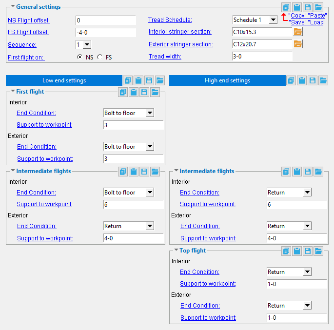
Quick Stair Add window settings (elevation views):
------ General settings ------
NS Flight offset: The positive or negative (-) distance (horizontal) (in the primary dimension "Units" or other units) that a near side stair's member line is to be offset from the work plane in which the stair is added.
An entry of '0' (zero) means that the stair's member line is not offset from the work plane.
A 'positive distance' offsets the stair's member line into the view that the stair is added.
A 'negative (-) distance' offsets the stair's member line out of the view.
Note: When "First flight on" is 'NS', the first stair that you add is the near side stair. Before you right-click (Return), the third stair, the fifth stair, etc. that you add will also be near side stairs.
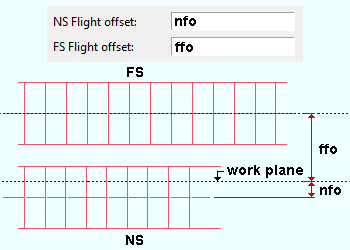
FS Flight offset: The positive or negative (-) distance (horizontal) (in the primary dimension "Units" or other units) that a far side stair's member line is to be offset from the work plane in which the stair is added.
Note: When "First flight on" is 'FS', the first stair that you add is the far side stair. Before you right-click (Return), the third stair, the fifth stair, etc. that you add will also be far side stairs.
'NS' places the first flight that you add on the near side; that is, its member line is placed using the "NS offset" distance.
'FS' places the first flight that you add on the far side; that is, its member line is placed using the "FS offset" distance.
Interior stringer section: The section size of the interior stringer. Allowable materials for stringers are channel (C) or tube steel (TS) or plate (e.g., ' PL3/8x14 ').
To enter a section size, either type in the section size that you want, or press the "file cabinet" button (
Typing in plate material: Rectangular plate material is designated by "Plate" prefix+ thickness x width (example: PL3/8x14 ).
Stair Edit window: "NS Material" or "FS Material"
Exterior stringer section: The section size of the exterior stringer. Allowable materials are the same as for the "Interior stringer section."
Stair Edit window: "NS Material" or "FS Material"
|
End condition: No return or Return or Bolt to floor or Top cap.
'No return' cuts the stair stringer vertically. The cut is in vertical alignment with the stair workpoint when "Support to workpoint."
'Return' adds a horizontal return, the length of which is based on the "Support to workpoint" distance.
'Bolt to floor' cuts the bottom end of the stair stringer so that it is horizontal and can, therefore, lay flat on a floor. This applies when the "End condition" is among the [Low end settings].
'Top cap' cuts the top of the stringer flat and adds a top cap plate. The plate may be extended based on the "Support to workpoint." This applies when the "End condition" is among the [High End Settings].
Stair Edit window: "End Condition"
Support to workpoint: The distance (horizontal) (in the primary dimension " Units " or other units ) from the supporting member (e.g., beam) to the work point of the stair.
|
The work points of a stair are aligned, by default, with the nosing line of the stair treads. |
Stair Edit window: "Support to workpoint"

