Change Load Options ( Home & Modeling & Drawing Editor )
Tool summary :
Also see :
- Process and Create Solids (to apply load changes to the model)
page 1 | contents | change options | edit > | drawing editor
Example :

|
1 . Select the type of load you want to change (in this case, " Shear load "). Specify the value to change to (in this case, " Auto "). |

|
2 . Select the members to which you want the load specified in step 1 to be applied. |

|
3 . The load is automatically applied to the selected members. |
page 1 | contents | change options | edit > | drawing editor | top
Step-by-step instructions :
Change Load Options lets you change loads on member edit windows ( Beam Edit or Column Edit or Horizontal Brace Edit or Vertical Brace Edit ) -- all without your ever having to open these windows.
1 . Invoke Change Load Options using any one (1) of the following methods:
Method 1 : Home > Utilities > Utility Functions > Change Options > Change Load Options .
Method 2 : Click the Change Load Options icon. The icon can be taken from the group named ' Edit -- Change Options ' and placed on a toolbar (classic) or the ribbon (lightning).
Method 3 : If the " Modeling layout style " or " Drawing Editor layout style " is ' Classic ', you can use the menu system to choose Edit > Change Options > Change Load Options .
Method 4, 5 & 6 : Change Load Options can also be configured to be invoked using a keyboard shortcut , the context menu , or a mode . For the lightning interface, this configuration is done using Customize Interface .
2 . The Change Load Options window opens.
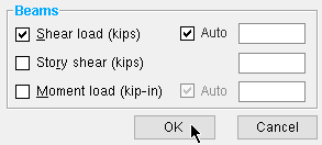
2a : In the left column of this window, check the box (
) for each type of load you want to change.
2b : To the right of each load type checked in step 2a, specify the load you want applied to the members that you will select in step 3.
2c : Press the " OK " button at the bottom of this window to go to step 3.
| Beams | ||
| Load Type | Change To | Effect |
| Shear load | Auto or a user entry in kips or kN | Auto instructs connection design to calculate the shear load based on the percent of uniform allowable load or maximum web shear entered to " Beam design reaction " in Design Settings . |
| Story shear | a user entry in kips or kN. |
Affects beam to a column flange connections when " |
| Moment load | Auto or a user entry in kips-in or kN.m | Auto instructs connection design to calculate the moment load based on the " Percent of maximum allowable moment " in Design Settings. |
| Tension load | a user entry in kips or kN. | May be used in the design of clip angle or end plate or single-plate shear (shear tab) connections. |
| Compression | a user entry in kips or kN. | May be used in the design of clip angle or end plate or single-plate shear (shear tab) connections. |
| Columns | ||
| Load Type | Change To | Effect |
| Load | Auto or a user entry in kips or kN | If stiffeners are desired in beams over or under columns, a load must be entered for the column end that contacts the beam. |
| Moment | Auto or a user entry in kips-in or kN.m | Moment loads are used in the design of column splices only. |
| Splice uplift | Auto or a user entry in kips or kN. | Splice uplift is used in the design of column splices only. |
| Horizontal braces | ||
| Load Type | Change To | Effect |
| Tension load | Auto or a user entry in kips or kN | " Brace design tension. . . % of allowable load " in Design Settings is used for Auto. |
| Compression | Auto or a user entry in kips or kN | " Brace compression ...% of allowable load " in Design Settings is used for Auto. |
| Vertical braces | ||
| Load Type | Change To | Effect |
| Tension load | Auto or a user entry in kips or kN | " Brace design tension. . . % of allowable load " in Design Settings is used for Auto |
| Compression | Auto or a user entry in kips or kN | " Brace compression ...% of allowable load " in Design Settings is used for Auto. |
3 . A selection dialog opens. On it is a list with a list of all members whose load entry fields currently have a load setting that does not match the load setting you entered in step 2. Note that the type of change to be made to the members is in the title of the window. Exception: Instead of a selection dialog, you may get a notification message stating that no loads of the type searched for could be found -- in which case you are done.
![]()
![]()
Alternative 1 : Select any one member or any group of members whose edit windows you want changed, then press " OK ." Go to step 4 or step 5.
Alternative 2 : Press the " Cancel " button if you do not want to change the loads for any of the members listed. At this point you will either be done with this Change Load Options operation, or go to step 5.
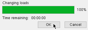
4 . The change you specified will be made to each of the members you selected (and to their Beam Edit or Column Edit or Horizontal Brace Edit or Vertical Brace Edit windows). A progress bar appears on screen as these changes are made.
![]()
4a : Press the " OK " button when the progress bar reaches 100%. At this point you will either be done with this Change Load Options operation, or go to step 5.
5 . If you made more than one entry in step 2, then the selection dialog (or a notification message) for the next highest entry made on the Change Load Options window (in step 2) will open. Repeat step 3 .
Tip: When you are done changing loads, you will probably want to Process and Create Solids to cause the connections on the affected members to be redesigned.
page 1 | contents | change options | edit > | drawing editor | top


