 Material Add Turnbuckle Element
See on another page: Turnbuckle Material window
- Step-By-Step
- Tips and Tricks
- Related Tools
1 . Click the Material Add Turnbuckle Element icon, which is pictured above. The icon can be found on the Material page > Add section. Select a member you want to add the material to.
▸ Preselect a Member to enable the Members contextual page and click the Material Add Turnbuckle Element icon found in the Materials/Components section.
Alternative: Invoke Material Add Turnbuckle Element using the Find Tool by searching the command name and clicking the icon, which is pictured above.
Learn more about alternative methods for launching commands.
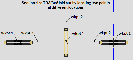
2 . The status line prompts, "Add: Material". Locate- Pan -Return mouse bindings become active. Select the appropriate Locate option, then left-click (Locate) at two different points to define the work line (and X material axis) of the turnbuckle. The first point you select locates the center of the turnbuckle. The second point sets the direction of the turnbuckle. The length of the turnbuckle is set by your project's local shape file. The turnbuckle material is centered on its XYZ material axis by default.
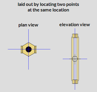
Alternative: Left-click (Locate) twice at the same location to define a cross section of the turnbuckle material. The material's workline will be perpendicular to your current view. The first left-click establishes the material's origin point at the work plane of your view. The material extends toward you from the its origin point.
3 . The Turnbuckle Material window opens. On it are settings for the turnbuckle you are adding. When you are done changing or reviewing the settings, press the "OK" button to close the window.
Alternative : Press "Cancel" to back up to step 2. This stops the turnbuckle from being added.
4 . The Rotate Material window opens, and a preview of the to-be-added turnbuckle is shown on screen. Do one (1) of the following:
Alternative 1 : To accept the material's present rotation, press the "OK" button.
Alternative 2 : Change the material's rotational settings and then press "OK" if you want to rotate the material.
Alternative 3 : Press "Cancel" to back up to step 2. This stops the turnbuckle material from being added.
5 . The status line prompts, "Locate material dimension reference point". Left-click (Locate) the reference point at the desired location or Right-click (Enter) to place the reference point at the first work point you located in step 2.
6 . The status line prompts "Add: material". The Locate - Repeat - Return mouse bindings become active.
Alternative 1 : Repeat steps 2-5 if you want to add a turnbuckle that is different than the one you just added.
Alternative 2 : Middle-click (Repeat) if you want to add a turnbuckle that is exactly like the one you just added.
Alternative 3 : Right-click (Return) to add the turnbuckle material to the model and end the command.
Note : If the material was added to a member with like members, the Material Add -- Options window appears and gives you the option to add the material to like members. After making your choice here and clicking OK, the material is added to the model and the command ends.
- The turnbuckle becomes a submaterial of the member that you select to add it to.
- If you do not want the turnbuckle shop attached to a member, you can add it as a miscellaneous member.
- Turnbuckle material must be in your local shape file in order for you to be able to add a turnbuckle. Use Home > Utilities > Shapes Properties to add turnbuckle material if there currently is no such material in your local shape file. The Copy Shapes utility can also be used to add turnbuckle material to the local shape file.
- The turnbuckle's "Section size" defines a turnbuckle's basic dimensions and weight. Other key entries you need to make on the Turnbuckle Material window are "Left thread type", and a "Right thread type".
-
A rod brace can be constructed with two clevises, a turnbuckle, plates and round bars. You can add rod bracing similar to this by entering a round bar description as the "Section size" on the Vertical Brace window.
- Turnbuckle Material window
- Turnbuckle Edit window (Misc. member)
- Parametric information for Turnbuckle material
- Turnbuckle material (Topic)
- Vertical Rod Bracing (Vertical Brace connection guide)
- Add Miscellaneous Member
- Miscellaneous Member Edit window (General settings and related topics)
- Miscellaneous Steel (Default misc. member types)
- Legacy Miscellaneous Member Edit window
- Settings on material windows for Add Legacy Miscellaneous Member
- Legacy Miscellaneous Steel (Legacy misc. member types)

