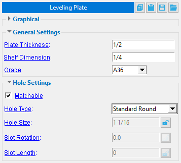
 Leveling Plate ( Modeling ) (a custom component )
Tool summary :
-
Default settings can be set up for the window shown above. See Home > Project Settings > Job > Component Plugin Defaults > Leveling Plate .
-
On this page, see to add, edit or delete and component settings.
Also see :
- SDS2 Toolbox: Leveling Plate (YouTube) (
 )
)
page 1 | contents | model > component > add > | toolbox
To add, edit, or delete a Leveling Plate custom component:
page 1 | contents | model > component > add > | toolbox | top
------ General settings ------
Plate Thickness: The Thickness (in the primary dimension "Units" or other units) of the Leveling Plate being added/edited.
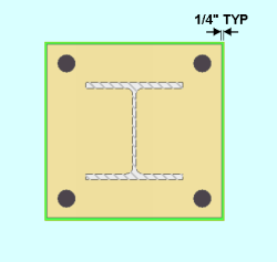
Shelf Dimension: The overhang of the Leveling Plate relative to the base plate (see example below, where Shelf Dimension = 1/4"). This controls the overall size of the Leveling Plate. It allows you to add to every side of the plate, using the base plate as a reference. You can also enter a negative dimension to make the Leveling Plate smaller than the base plate.
Grade: This is the grade of steel for the Leveling Plate whose settings are defined on this window.
Setup: If the grade of steel you want is not shown in the list box (
), you can use Home > Project Settings > Job > Material Grades > Plate Grades to add it to this list.
------ Hole settings ------
Matchable:
![]() or
or ![]() . If this box is checked (
. If this box is checked ( ![]() ) and the hole(s) are in a material that is face-to-face with the base plate material, the Model > Hole > Match to match the hole(s) to a different material.
) and the hole(s) are in a material that is face-to-face with the base plate material, the Model > Hole > Match to match the hole(s) to a different material.
If the box is not checked (
), the hole(s) will not be matched to other material during Model > Hole > Match or during the matching holes phase of Create Solids.
Note: Certain " Hole types " are, by default, set to not matchable ("
Hole Type: Choose Standard round or Short slot or Oversized round or Long slot or Cope hole or Erection pin hole or Anchor bolt hole or Plug weld hole or Grout or User slot #1 or User slot #2 or Vent/Drain.
A ' Standard round ' hole is perfectly round and has a " Hole diameter " that is typically 1/16 inch larger than the " Bolt diameter ." See Table J3.3 or Table J3.3M ( AISC Thirteenth Edition , p. 16.1-105).
A ' Short slot ' hole is oblong in shape and has a relatively short " Slot length " (1 5/16 inch for a 1 inch diameter bolt).
An ' Oversized ' hole will typically input a " Hole diameter " 3/16 inch larger than the " Bolt diameter ."
A ' Long slot ' hole is oblong in shape, has a diameter 1/16 inch larger than the input bolt diameter, and has a relatively long " Slot length " (2 1/2 inch for a 1 inch diameter bolt).
A ' Cope hole ' is for using a punch or drilling machine instead of a cutting machine to cope a piece of material. By default, cope holes are not matchable ("
An ' Erection pin hole ' is a hole on the end of a column for use by a crane to lift the column into place (see show erection pin holes on columns ). By default, erection pin holes are set to be not matchable ("
An ' Anchor bolt hole ' is a hole for anchor bolts in a column base plate. Holes must be of this type in order for them to be automatically dimensioned when the " Dimension anchor bolt layout " option is selected during erection view regeneration. By default, anchor bolt holes are not matchable ("
A ' Plug weld hole ' is for adding to a material before the material is plug welded . By default, plug weld holes are not matchable ("
A ' Grout ' hole may be used for pouring grout under a base plate. By default, vent/drain holes are not matchable ("
' User slot #1 ' and ' User slot #2 ' are slots whose " Slot length " are set, based on the " Bolt diameter ," from user-entered length settings maintained at Home > Project Settings > Job > User Slot Lengths .
Hole Size: A system-calculated or user-entered distance that will be the diameter of the hole(s) modeled in the Leveling Plate.
Slot Rotation: A positive or negative number from 90 to -90 degrees. This applies when the "Hole type" is 'Long slot' or 'Short slot'. Slot rotations can be modeled to a precision of 0.1 degree.
Slot Length: The system-calculated or user-entered distance (in the primary dimension "Units" or other units) between the two points farthest from one another on the perimeter of a slot.
page 1 | contents | model > component > add > | toolbox | top