 Process Selected Members ( Modeling & Drawing Editor )
Tool summary :
Also see :
- Process and Create Solids (alternative to Process Selected Members )
- Create Solids for Selected Members (completes Process Selected Members )
- Process within member edit (makes Process Selected less frequently necessary)
- Mark Members for Processing (alternative for selecting members)
- Detailing and processing > Needs to be processed ( Status Display )
page 1 | contents | process > | process | top
 Step-by-step instructions :
This option is for users who would like to divide Process and Create Solids into parts and select which members to process (instead of having Process and Create Solids automatically select members).
1 . Invoke Process Selected Members using any one (1) of the following methods:
2 . A selection dialog opens. On it is a selection list of all members that have been created in your current Job . Members that have not been Processed or have changed since they were last Processed are automatically selected on the list.
|
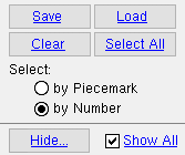
" Hide ... " and " Show All " can be used to adjust which classes of members are shown on the selection list. " |
Alternative 1 : If you want to edit only one member, double-click the number or piecemark of that member. Go to step 3.
Alternative 2 : Select multiple members, then press " OK " to continue to step 3.
Alternative 3 : Press the " Cancel " button to end the Process Selected Members operation. Do not continue.
3 . A progress bar appears on screen to graphically illustrate that processing is taking place.
3a : When the progress bar reaches 100%, the progress bar window will close automatically if the box is checked (
) for " Close when done ." If the window does not close automatically, you can close it by checking that same box or by pressing the " OK " button.
4 . Skip this step if it does not apply. Process Only at this point opens a notification window that says, "Due to certain framing situations encountered during this process operation, additional members have now been marked for creating solids and piecemark assignment." The notification window also tells you what phases of Process and Create Solids the member has been marked for.
4a : Press the " OK " button to dismiss the notification window.
5 . Things you can do in Modeling after Process Selected Members :


