 Add Safety Holes ( Modeling )
Tool summary :
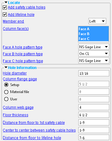
This window opens when you add safety holes. To access this window for editing the safety holes, you can edit the beam or use the Model Tree .
The first time a new Safety Holes component is added in a new Modeling session, this window is populated with default settings per choices made in Home > Project Settings > Job > Component Plugin Defaults > Component Plugin Setup .
- See, on this help page, to edit or delete the custom component .
Also see :
|
|
- Modeling (where custom components can be added)
- Column Safety Cable Holes Setup ( Home > Project Settings > Job > Component Plugin Defaults >)
- Custom components (topic)
- Copy Component (to copy the component to another beam, its holes to another column) **
- Move Component (to move the component to another beam, its holes to another column) **
- Explode Component ( cannot on the Safety Holes custom component)
- Component Selection Tool (to search for custom components of a selected type)
- Model Tree (to find custom components and select them for deletion, editing, etc.)
** For Copy Component and Move Component operations on a Safety Holes custom component, preselection of the component in the Model Tree is required. You cannot select the Safety Holes component in the model. You can select the holes in the model, but not the component.
page 1 | contents | add component | model > component > | top
 To edit or delete the custom component :
- To edit a Safety Holes component, you can open its Beam Edit window. The component's settings will be contained in that window in a section named [ Safety Holes ]. To edit a Safety Holes custom component without opening the Beam Edit window, use the Model Tree . The Component Selection Tool can also be used to edit (and find) custom components.
page 1 | contents | add component | model > component > | top
 Safety Holes custom component settings :
![]() Locate --------------------------------------------------------------------------------
Locate --------------------------------------------------------------------------------
If this box is checked (
), safety cable holes will be added to each of the " Column face(s) " that you select. Their placement will be governed by the " Floor thickness " and " Distance from floor to 1st safety cable " and the " Center to center distance between safety cable holes ."
If the box is not checked (
), safety cable holes will not be added.
If this box is checked (
), a lifeline hole will be added to each of the " Column face(s) " that you select. Their placement will be governed by the " Floor thickness " and the " Distance from floor to lifeline hole "
If the box is not checked (
), lifeline holes will not be added.
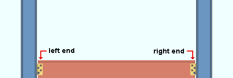
' Left End ' results in the safety holes being generated on the column that is framed to by the left end of the beam. On the Beam Edit window, the component's will appear under the left-end settings in a leaf that is named "
Safety Holes ."
' Right End ' results in the safety holes being generated on the column that is framed to by the right end of the beam. On the Beam Edit window, the component's settings will appear under the right-end settings in a leaf that is named "
Safety Holes ."
Column face(s): Face A and/or Face B and/or Face C . You must select at least one face to get holes.
|
face A |
|
|
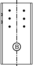
' Face B ' is web near side of the column.
' Face A ' is the left flange when you are looking at face B.
' Face C ' is the right flange when you are looking at face B.
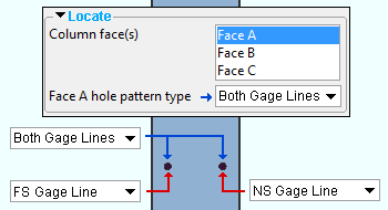
Face A hole pattern type: Near Side Gage Line or Far Side Gage Line or Both Gage Lines . This applies when ' Face A ' is selected as one of the " Column face(s) ." The positions of the near side and far side gage lines are based on the " Column flange gage ."

|
|
' Near Side Gage Line ' places the hole(s) along the near side gage line.
' Far Side Gage Line ' places the hole(s) along the far side gage line.
' Both Gage Lines ' places the hole(s) along both the near side gage line and far side gage line, resulting in your getting twice as many flange holes than you have gotten if you had selected just a single gage line.
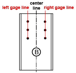
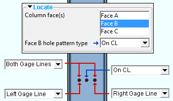
Face B hole pattern type: On CL or Left Gage Line or Right Gage Line or Both Gage Lines . This applies when ' Face B ' is selected as one of the " Column face(s) ." The positions of the left and right gage lines are based on the " Column web gage ."
|
|
' On CL ' places the hole(s) along the center line of the column web.
' Left Gage Line ' places the hole(s) along the left gage line of the near side of the column web.
' Right Gage Line ' places the hole(s) along the right gage line of the near side of the column web.
' Both Gage Lines ' places the hole(s) along both the left gage line and the right gage line of the near side of the column web, resulting in your getting twice as many flange holes than you would have gotten if you had selected a single gage line or the center line.
Face C hole pattern type: Near Side Gage Line or Far Side Gage Line or Both Gage Lines . This applies when ' Face C ' is selected as one of the " Column face(s) ." The positions of the near side and far side gage lines are based on the " Column flange gage ."

![]() Hole Information ----------------------------------------------------------------
Hole Information ----------------------------------------------------------------
Hole diameter: The diameter of the safety cable holes and/or lifeline hole (in the primary dimension " Units " or other units ).
![]()
Column flange gage: The distance (in the primary dimension " Units " or other units ) between the near side and far side gage lines on the flange. These gage lines are equidistant from the center line of the column. The gage that is defined here applies when ' Face A ' and/or ' Face C ' are selected as one or two of the " Column face(s) ."
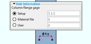
Column web gage: The distance (in the primary dimension " Units " or other units ) between the left and right gage lines on the near side web (face B) of the column. .The gage that is defined here is centered on the half-depth of the column and applies when ' Face B ' is selected as at least one of the " Column face(s) ."

Floor thickness: The distance (in the primary dimension " Units " or other units ) from the top of the beam to the surface of the floor. The " Distance from floor to 1st safety cable " and " Distance from floor to lifeline hole " are measured from the floor surface. In the example below, this distance is ft .
Distance from floor to 1st safety cable: The distance (in the primary dimension " Units " or other units ) from the surface of the floor to the center of the 1st (lowest) safety cable hole. In the example below, this distance is h1 .
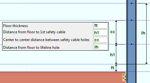
Center to center distance between safety cable holes: The distance (in the primary dimension " Units " or other units ) from the center of the 1st (lowest) safety cable hole to the center of the next safety cable hole. In the example below, this distance is cc .

Distance from floor to lifeline hole: The distance (in the primary dimension " Units " or other units ) from the floor to the center of the lifeline hole. In the example below, this distance is lh .

page 1 | contents | add component | model > component > | top


