Step 5: Reviewing the 3D Model (topic)
- Introduction
- Two ways of reviewing the 3D model
- Tips for visually examining the 3D model
- Searches to review member edit windows (
 )
)
- Using reports to review the 3D model
Introduction :
page 1 | contents | overview | top
Two methods of reviewing the 3D model :
Method 1: Visual inspection. One way to review how connections have been designed is to enter Modeling (
) to view the 3D model in any of the three solid forms . Visually examining the 3D model in Modeling is an excellent way to catch glaring errors as well as to see subtleties of design that would otherwise be difficult to visualize. For more information, see tips for visually examining the 3D model .
Method 2: Review settings. Much information about the 3D model can be obtained from various member, material, bolt, hole and weld edit windows. For instance, double-clicking on a member opens that member's beam , column , vertical brace or horizontal brace edit window. The edit window tells you, for example, how the program has designed connections. Member edit windows are also opened when you do Searches for members with, for instance, Failed Connections (
) or Braces with Different Thickness Gussets (
). Just double-click a member on the list of member piecemarks that appears when you do a Search . to open the edit window for that member. The most detailed of connection settings are reviewed using the connection design locks that may be found on member edit windows or on Connection Component Edit windows). For more information, see searches to review member edit windows .
page 1 | contents | overview | top
Tips for visually inspecting the 3D model :
Reviewing the 3D model is easiest in an isometric view , as this type of view lets you see more surfaces than does a in a plan view or elevation view .
VIDEO 
View > Isometric View followed by Save View As are used to save an isometric view.
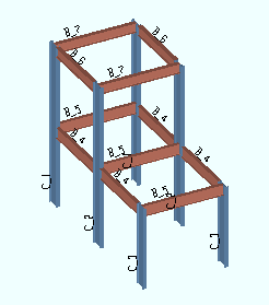
Shown at left is an isometric view of a model displayed in solid opaque form. Changing between stick and various solid forms can be done using options on the View menu in Modeling .
VIDEO 
An introduction to the various stick and solid forms. The default keyboard shortcut s a is used to change all members to solid opaque. Some members are selected by area box , then turned to solid by right-clicking and choosing " Solid Opaque " on the context menu.
stick 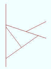
solid 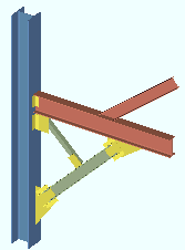
Any of the three solid forms show connections. You can see through the main material of members when the members are displayed in transparent or transparent main form.
|
|
|
||
| solid opaque
|
solid transparent
|
solid transparent main |
Solid opaque = opaque main material & connection material.
Solid transparent = transparent main material & connection material.
Solid transparent main = transparent main material, opaque connection material.
To switch from view to view while you are in Modeling , Open ( Ctrl + o ) or double-click the name of a straight grid line such as "Grid X" in the example below.
|
The selection filter needs to be set to ' Default ' in order for double-click to open the view when you double-click a straight grid line's name. "X" is the name of the view in this example. |
|
||||||||||||||||
| The axes boxes in the above illustration show the orientation of global axes as you go from view to view. | ||||||||||||||||
To zoom in and zoom out of views, use your mouse wheel . If you don't have a mouse wheel, other zoom options (such as Zoom In to Region ) are available on the Navigate menu.
zooming in 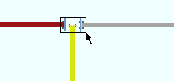
after zooming in 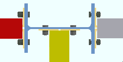
To scroll across the screen, use the scroll bars around the Modeling drawing area, or use Pan .
Your mouse pointer ( ) becomes a 4-way mouse pointer (
) when you Pan .
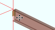
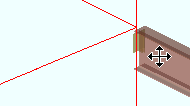
To rotate around a member, use Rotate .
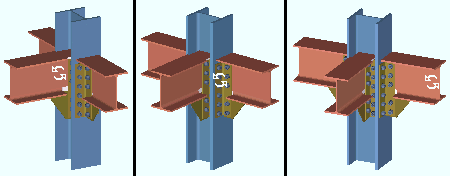
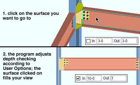
In this example of Rotate , the mouse pointer is dragged horizontally, thus rotating the view around the column. Surface tools such as Snap to Surface (illustrated below) or Snap to Far Side Surface or Snap to Adjacent Surface can bring you to surface which can or cannot be seen in your current view.
VIDEO 
Snap to Surface is used to relocate the work plane of a view.
To undo view changes, you can use Undo View Change or Revert .
To save view changes as permanent erection views, you can Save View As . You'll get best results saving view transformations made using Isometric View (
) or Plan View (
) or Section View or Rotate View or Snap to Surface or Snap to Farside Surface or Snap to Adjacent Surface or Reference Elevation or Relative Depth .
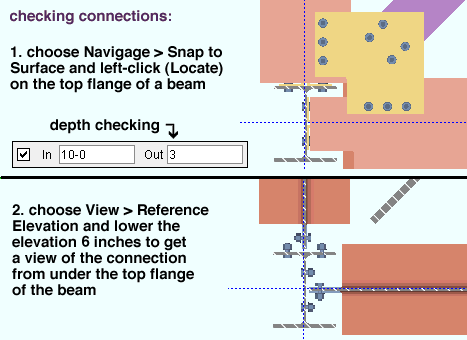
An excellent way to check connections is to invoke Snap to Surface , left-click ( Locate ) on the top flange of the beam whose connections you want to look at, use your middle mouse button to Pan over to above the connection, then lower the elevation so that your perspective is from underneath the beam flange.
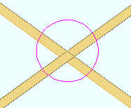
Doing a Clash Report ( Reports > Clash Report ) identifies materials that overlap as much or more than a specific tolerance that you specify. The area where the two materials "clash" is circled as shown below:
Status can help you to narrow your search for items such as members with failed connections (
). Choose Model > Status Display (
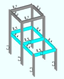
) to set status display options. In the example below, Status Display was used to display W16x31 member section sizes in the color cyan:
Find Material lets you locate material by its submaterial mark . Choose Model > Material > Find Material , then select a submaterial mark. Members containing the submaterial mark you selected are then isolated from other members in your current view. The selected submaterial is displayed in cyan, while the rest of the member remains its normal color. In the example below, the selected submaterial is an angle:
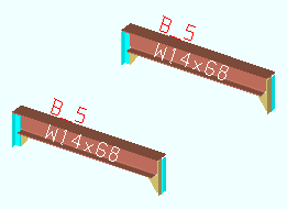
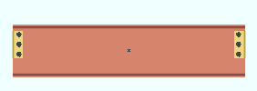
Isolating a single member lets you view a member separately from other members in the model. Choose Model > Member > Isolate Member to do this. Available views of the isolated member correspond to views shown on the member's detail. If you create additional views, those views will also be shown on the member detail (after Detail Members ).
page 1 | contents | overview | top
Searches to review member edit windows :
After Constructing a 3D Model , you need to ensure that all system connections have been designed the way you want them to be. Toward this end, SDS2 provides a number of searches. These searches may be done in Modeling or the Drawing Editor by choosing Process > Search . Some of these searches are listed below:
Failed Connections (
) is a search for members for which connection design was unable to design a system connection that would stand up to the specified or calculated load. On the beam , column , vertical brace or horizontal brace edit window for that member, you will find a connection failure message such as that shown below. Beam , column , horizontal brace and vertical brace end connection failure messages can give you clues about steps you can take to generate a connection that will not fail.
![]()
|
Connections Below Minimum Setup is a Search for beams on which the number of bolt rows are less than the minimum number of bolt rows that are specified under Home > Project Settings > Job in the Structural Members Schedule of Minimums for a beam with that particular nominal depth. The Search also looks for welds that are less than the Home > Project Settings > Job > Weld Design Settings > " Minimum weld size for this job ."
Bolt Diameters Changed by System is a search for members with connections whose bolt diameters have been increased by connection design in order to design a system connection that would stand up to the specified or calculated loading conditions.
Braces with Different Thickness Gussets (
) is a search for braces in the 3D model for any and all braces whose gusset plate on one end has a different thickness than the gusset plate on the other end.
VIDEO 
The search for Braces with Different Thickness Gussets is done together with resetting the " Minimum gusset thickness " in order to make a member's gussets the same thickness. The term "revise & review" field is, in v2015 and newer versions, superseded by the term " connection design lock " or "lockable." Indeterminate Ends is a search for members with ends that do not frame into anything (plain ends). When you go to the member edit window ( Beam Edit window or Column Edit window or Horizontal Brace Edit window or Vertical Brace Edit window or etc.) for a particular member that has been found in this search, you will find that the field " System designed connection " for at least one end of the member will read ' Plain end '.
page 1 | contents | overview | top


