 Add WWF Beam Lifeline Holes ( Modeling )
Tool summary :

Lifeline holes may be added to the top and/or bottom flanges of the beam, to the near side and/or the far side of those flanges.
To edit the custom component, you can edit the beam or use the Model Tree to open the WWF Beam Lifeline Holes window.
On the beam's edit window, the settings that control the lifeline holes are stored in the [ WWF Beam Lifeline Holes ] section .
- See, on this window, to add, edit or delete the custom component .
Also see :
- Modeling (where custom components can be added)
- Custom components (topic)
- Copy Component (to copy the component to another member) **
- Move Component (to move the component to another member) **
- Explode Component ( cannot be done on the WWF Lifeline Holes custom component)
- Component Selection Tool (to search for custom components of a selected type)
- Model Tree (to find custom components and select them for deletion, editing, etc.)
** For Copy Component and Move Component operations on a WWF Beam Lifeline Holes custom component, preselection of the component in the Model Tree is required. You cannot select the Lifeline Holes component in the model. You can select the holes in the model, but not the component.
page 1 | contents | add component | model > component > | top
 To add, edit or delete the WWF Beam Lifeline Holes custom component :
A WWF Beam Lifeline Holes custom component can be added to any beam whose " Section size " is a welded plate wide flange section. WWF stands for welded plate wide flange. The custom component can add holes to the top or bottom flanges of the WWF beam.
To add the custom component: 1 ) In Modeling , select a welded plate wide flange beam. 2 ) Choose Model > Component > Add or click the icon. 3 ) On the custom component selection list, choose " WWF Beam Lifeline Holes " as the custom component you want to add. 4 ) The WWF Beam Lifeline Holes window opens. Specify the location of the lifeline holes, then press " OK ." 5 ) If User and Site Options > Modeling > " Automatically process after modeling operation " is set to ' Process and create solids ', the lifeline holes will be generated immediately. If not, the lifeline holes will be generated on the welded plate wide flange beam the next time that beam undergoes Process and Create Solids .
Tip: If you use in-tool selection -- that is, select the member after selecting " WWF Beam Lifeline Holes " as the custom component you want to add -- only welded plate wide flange beams and columns and vertical braces will be selectable. To edit a WWF Lifeline Holes custom component, you can open its Beam Edit window. The section will be named [ WWF Beam Lifeline Holes ]. To edit a WWF Beam Lifeline Holes custom component without opening the member edit window, use the Model Tree . The Component Selection Tool can also be used to edit (and find) custom components.
To delete an WWF Beam Lifeline Holes custom component: 1 ) Select the component in the Model Tree . 2 ) Press the Delete key (or choose Edit > Delete ). 3 ) Process and Create Solids .
Another way to delete an WWF Beam Lifeline Holes custom component: 1 ) On the component's Beam Edit or Column Edit or Vertical Brace Edit window's navigation tree (left panel), select the " WWF Beam Lifeline Holes " section. 2 ) Right-click and choose " Delete " on the menu. The section will disappear. 3 ) Press the beam window's " OK " button to make the deletion of the component permanent.
In the Model Tree , the custom component will be listed under the member as WWF Beam Lifeline Holes when " View By " is set to ' Member piecemark ' or ' Member number '. The component will be listed under its beam, after that member's connection components ( Left End and Right End ), and before that member's submaterials, welds and bolts.
page 1 | contents | add component | model > component > | top
![]() WWF Beam Lifeline Holes custom component settings :
WWF Beam Lifeline Holes custom component settings :
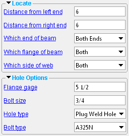
![]() Locate --------------------------------------------------------------------------------
Locate --------------------------------------------------------------------------------
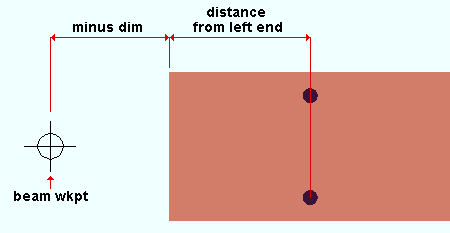
Distance from left end: The distance (in the primary dimension " Units " or other units ) from the left end of the beam's main material to the lifeline hole(s). This setting applies when " Which end of beam " is set to ' Left End ' or ' Both Ends '.

|
| The " Distance from left end " is taken from the left end of the beam's main material, not from the beam's workpoint. In this example, the beam's left-end main material setback is its left-end " Minus dimension " from its left-end workpoint. |
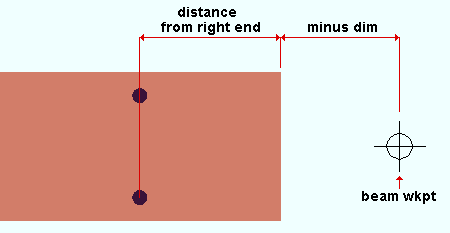
Distance from right end: The distance (in the primary dimension " Units " or other units ) from the right end of the beam's main material to the lifeline hole(s). This setting applies when " Which end of beam " is set to ' Right End ' or ' Both Ends '.

|
| The " Distance from right end " is taken from the right end of the beam's main material, not from the beam's workpoint. In this example, the beam's right-end main material setback is its right-end " Minus dimension " from its left-end workpoint. |
Which end of beam: Left End or Right End or Both Ends .
' Left End ' results in one, two or four lifeline holes being placed the " Distance from left end " from the left end of the beam's main material.
' Right End ' results in lifeline holes being placed the " Distance from right end " from the right end of the beam's main material.
' Both Ends ' results in lifeline holes being placed
Which flange of beam: Top or Bottom or Both .
' Top ' puts the lifeline holes on the top flange of the welded plate wide flange beam.
' Bottom ' puts the lifeline holes on the bottom flange of the beam.
' Both ' puts the lifeline holes on both the top and bottom flanges
Which side of web: NS or FS or Both .

|
| The top flange of the same beam is shown in each of these three examples. |
' NS ' places the lifeline hole(s) on the " Flange gage " line for the near side of the beam. If you are looking down on the flange and the left end of the beam is to your left, the near side of the flange is its bottom half.
' FS ' places the lifeline hole(s) on the " Flange gage " line for the far side of the beam. If you are looking down on the flange and the left end of the beam is to your left, the far side of the flange is its top half.
' Both ' places lifeline holes on both the " Flange gage " lines.
page 1 | contents | add component | model > component > | top
![]() Hole Options ----------------------------------------------------------------------
Hole Options ----------------------------------------------------------------------
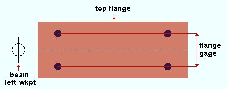
Flange gage: The distance (in the primary dimension " Units " or other units ) from the near side flange gage line to the far side flange gage line. These gage lines are equidistant from the beam workline.

|
| To get four lifeline holes in this pattern on the top flange of a beam, you could set " Which end of the beam " to ' Both Ends ', " Which side flange of beam " to either ' Top ' or ' Both ' and " Which side of web " to ' Both '. |
Bolt size: The diameter of bolt in the primary dimension " Units " or other units . The diameter you enter here sets the " Hole diameter " of the lifeline holes when the " Hole type " is ' Standard Round ' or ' Oversized '.
| diameter |
|
The diameter you enter here will become the " Bolt diameter " on the Hole Edit window for each of those lifeline holes.
Bolts are not added automatically. If you Match Holes to a material facing a standard round or oversized hole and choose to add bolts through those holes, the bolts that Match Holes or Process and Create Solids adds, by default, will be the " Bolt size " specified here. You cannot Match Holes with plug weld holes.
Hole type: Standard Round or Oversized Round or Plug Weld Hole . The choice you make here sets the " Hole diameter " of the lifeline holes.
A ' Standard round ' hole type is perfectly round and has a " Hole diameter " that is typically 1/16 inch larger than the input bolt diameter. See Table J3.3 or Table J3.3M ( AISC Thirteenth Edition , p. 16.1-105). For example, choosing ' Standard Round ' and setting the " Bolt size " to ' 3/4 ' inch will give you lifeline holes whose diameter is 13/16 inch.
An ' Oversized Round ' hole type typically inputs a " Hole diameter " 3/16 inch larger than the input bolt diameter. See Table J3.3 or Table J3.3M ( AISC Thirteenth Edition , p. 16.1-105). For example, choosing ' Oversized Round ' and setting the " Bolt size " to ' 3/4 ' inch will give you lifeline holes whose diameter is 15/16 inch.
A ' Plug Weld Hole ' inputs a " Hole diameter " that is, by default, 9/16 inch in diameter. Hole matching cannot be done on plug weld holes.
Bolt type: A490N or A490SC or A307 , etc.
This will be the " Preferred bolt type " on the Hole Edit window for each of the lifeline holes. Select from the list box (
) the type of bolt to be used. Bolt types listed on the menu come from the Bolt Specifications .
Bolts are not added automatically. If you Match Holes to a material that faces a standard round or oversized hole and choose to add bolts through those holes, the bolts that Match Holes adds will, by default, be the " Bolt type " specified here.
page 1 | contents | add component | model > component > | top


