 Viewport Add ( Drawing Editor )
Tool summary :
Also see :
- Viewport (to select a user-named viewport for a sheet item)
- Draw an area box from right to left (selects a viewport on the original drawing)
- Viewport Edit (to change the name of a user-named viewport)
page 1 | contents | objects > viewports > | objects -- viewports | viewports
 Example :
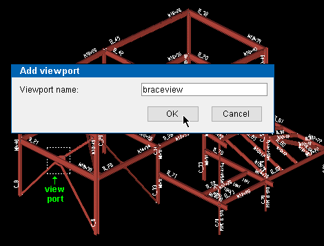
1 . Viewport Add on the original drawing.
|
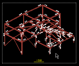
2 . Do an Sheet Item Add to place the original drawing as a sheet item . Double-click the sheet item to edit it.
|
The default viewport shown here is different than the one you added in the previous step. The shown viewport is the ' Extents ' viewport -- it displays the entire sheet item. |
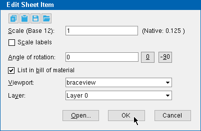
3 . Select the user-named viewport (' braceview ' in this example) as the " Viewport " on the Edit Sheet Item window.

|
In this example, the " Scale " was also changed (from ' 0.125 ' to ' 1 '). The original scale is the " Native " scale. |
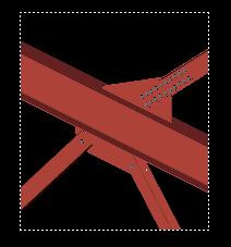
4 . The sheet item now displays only that part of the original drawing that is inside the ' braceview ' viewport, which was selected in step 3.
|
If you were to re-size or re-shape this viewport (named " braceview ") on the sheet item, it would be re-named to ' Custom '. If you re-size or re-shape it on the original drawing, it keeps its name, and it changes on all sheet items where ' braceview ' is the selected viewport. |
page 1 | contents | objects > viewports > | objects -- viewports | viewports | top
 Step-by-step instructions :
Viewport Add lets you add a user-named viewport to a member detail , submaterial , erection view or job standard detail . The viewport will be shown on that drawing as a white, dotted line.
1 . Open the drawing (member detail, submaterial, erection view or job standard detail) to which you want to apply the viewport.
2 . Invoke Viewport Add using any one (1) of the following methods:
Method 1 : Click the Viewport Add icon. The icon can be taken from the group named ' Objects -- Viewports ' and placed on a toolbar (classic) or the ribbon (lightning).
Method 2 : If " Drawing Editor layout style " is ' Classic ', you can use the menu system to choose Objects > Viewports > Add .
Method 3, 4 or 5 : Viewport Add can also be invoked using a keyboard shortcut , the context menu , or a mode . For the ' Lightning ' layout style, configuration of the interface is done using Customize Interface .
3 . Locate- Pan -Return mouse bindings become active, and the status line prompts, " Locate rectangular viewport bounds ."
|
|
|
bindings |
|
Method 1 & Method 2 describe two different ways of defining the area box for a viewport. |
Method 1 : Drag your mouse pointer (
) while holding down the left mouse button ( Locate ) to form an area box . Release the mouse button when the boundaries of the rectangular viewport are defined.
Method 2 : Place the mouse pointer (
) and left-click ( Locate ) to define one corner of the area box, then move the mouse pointer and left-click ( Locate ) to define the area box's opposite corner.
4 . The Viewport Add window opens.

4a . Type the " Viewport name " (up to 61 characters) that you want to be selectable (
) as the " Viewport " for sheet items that link to your current drawing. You can use blank spaces in the name. Press the " OK " button to continue.
5 . A new viewport is added. The boundaries of this viewport match the boundaries of the area box that you drew in step 3. Please note the following:
page 1 | contents | objects > viewports > | objects -- viewports | viewports | top


