The Clevis Material window ( Modeling ) (read-only)
Also see :
- Clevis (topic)
- General Information window (opened from this window)
- Submaterial piecemark (each unique material identified by)
- Submaterial detail (2D drawing of a material)
page 1 | contents | material review | material types | top
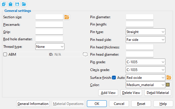
------ General settings ------
Section size: Any clevis section that is listed in the local shape file .
|
Piecemark: The submaterial piecemark ( up to 61 characters ) of the clevis whose specifications you are reviewing.
Tip: For the current quantity of materials that have been assigned this piecemark, see the " Current quantity " listed on this material's General Information window .
Grip: The distance (in the primary dimension " Units " or in other units ) between the prongs of the clevis.
Rod hole diameter: The diameter (in the primary dimension " Units " or in other units ) of the hole for inserting the rod.
Thread type: None or Left handed or Right handed .
Round Bar Material: Thread type
Turnbuckle Material: Left thread type and Right thread type
Pin diameter: The diameter of the shaft of the clevis pin (in the primary dimension " Units " or in other units ).
Pin length: The distance (in the primary dimension " Units " or in other units ) from one end of the clevis pin to its opposite end. The length of the pin includes its head.
Pin type: Straight or Headed or None .
' Straight ' specifies a clevis pin that is a consistent diameter along the entirety of its " Pin length ."
' Headed ' specifies a clevis pin with a head placed on the selected " Pin head side ." The size of the head is controlled by the entries made to " Pin head thickness " and " Pin head diameter ."
Pin head side: Near side or Far side .
' Near side ' puts the head on the far-side end of the clevis pin.
' Far side ' puts the head on the near-side end of the clevis pin.
Pin head thickness: The distance along the length of the pin to which the " Pin head diameter " is applied when when ' Headed ' is selected as the " Pin type ." Distances may be expressed in the primary dimension " Units " or in other units .
Pin head diameter: The diameter of the pin head (in the primary dimension " Units " or in other units ) when ' Headed ' is selected as the " Pin type ."
Pin grade: C-1035 or F22 Class3 or etc. Any grade of steel that is listed at Home > Project Settings > Job > Turnbuckle / Clevis / Pin Grades may be shown here as the steel grade of the clevis pin.
Clevis grade: C-1035 or F22 Class3 or etc. Any grade of steel that is listed at Home > Project Settings > Job > Turnbuckle / Clevis / Pin Grades may be shown here as the steel grade of the clevis.
Surface finish: None or Sandblasted or Red oxide or Yellow zinc or Gray oxide or Blued steel or Galvanized or Duplex Coating or Undefined 1 or Undefined 2 or Undefined 3 or Red oxide 2 or Any user added surface finish. This affects the colors of 'Solid ' members on erection views in the Drawing Editor . This also sets the color when "Output material color " is set to 'Surface finish ' for a VRML Export or a DWG/DXF Export . The "Color " ( not "Surface finish ") sets the color of this material in Modeling .
| sand blasted | red oxide | yellow zinc | user surface finish 1 |
| gray oxide | blued steel | galvanized | user surface finish 2 |
To assign a different surface finish, you can drop-down the current surface finish and select the one you want, or you can press the "file cabinet" browse button (
) and double-click any surface finish that is on the list.
Auto ![]() or
or ![]() .
.
If this box is checked (
), the material surface finish follows what is set on the member level.
If the box is not checked (
), the material surface finish can be changed to whatever is available in the list of surface finishes. If the surface finish changes from what the member level has set, the auto checkbox will be unchecked automatically. When the auto check box is unchecked, the member edit window shows an information tag which notifies the user that an attached material is not following what was set on the member level.
Note 1: Submaterial piecemarks can be split apart by surface finish. All surface finishes that do not have the 'Break Marks Material' checked on can be applied to any like material with out the material splitting. If the 'Break Marks Material' is checked on then only like materials with that specific surface finish can have the same piecemark, and because the submaterial marks differ so would the member's piecemark.
Note 2:When exporting a KISS file using "model" as the "Data source " surface finish data on the materials are compiled into the KISS download as follows, with a few exceptions (G=galvanized, N= none or sandblasted, P= others). Those exceptions are:
If the box for "Finish" routing in KISS export setup is set to a user routing
If the user has adjusted the Abbreviation for any of the default provided surface finishes
If you are using a user added surface finish
In these cases you will get what is provided in either the User routing, or the abbreviation field. For other exports it will always provide the abbreviation in the 'surface finishes' settings page.
Tip 1: "Surface area" is reported on the General Information window -- and this can be used to estimate the amount of coating required and its cost.
Tip 2: Changing "Steel grade " "Color " and "Surface finish " do not cause the plate to be regenerated. This means that, if you change those settings only, material fit operations such as a Fit Exact may, optionally, be preserved.
Report Writer:MemberMaterial.Material.SurfaceFinish
Setup:Surface Finish Settings
Color: The color of the clevis when it is displayed in a solid form . Different colors may be assigned to materials that have the same submaterial piecemark . The color swatch next to the list box ( ![]() ) displays the color that is selected.
) displays the color that is selected.
Setup: The default colors for member main materials and submaterials is set up on the Modeling Colors setup window.
page 1 | contents | material review | material types | top
To close this window :
![]()
![]()
" General Information " opens the General Information window, which you can use to review additional information about the selected material. Also, the " Properties " button is enabled on that window.
Pressing " Close " on the General Information window to close that window and reactivate this window.
"OK" (or the Enter key) closes this window.
page 1 | contents | material review | material types | top