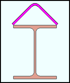
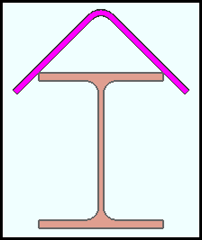
Beam Ridge Plate (a custom component )
|
|
The Beam Ridge Plate custom component can be added to an wide flange or HSS/TS beam. One way to edit the ridge plate is to open the Beam Edit window. You will find these settings in the [Beam Ridge Pate ] section. Another way is to double-click a ridge plate material or weld with the " Selection filter " set to ' Default ' or ' All ' or ' Custom Components ''. If User and Site Options > Modeling > " Automatically process after modeling operation " is set to ' Process and create solids ', the beam ridge plate is generated immediately after you press " OK " to close this window. If not, the ridge plate will be generated the next time the beam that this component belongs to undergoes Process and Create Solids . |
Also see :
- Modeling (where custom components can be added)
- Setup Beam Ridge Plate ( Home > Project Settings > Job > Component Plugin Defaults > )
- Custom components (topic)
- Copy Component (to copy the ridge plate to another beam)
- Move Component (to move the ridge plate to another beam)
- Explode Component (to reduce the component to its constituent materials and welds)
- Component Selection Tool (to search for custom components of a selected type)
- Model Tree (to find custom components and select them for deletion, editing, etc.)
Tips for adding a beam ridge plate :
![]() Material specifications ----------------------------------------------------------------------
Material specifications ----------------------------------------------------------------------
Graphical : ![]() or
or ![]() .
.
- A Beam Ridge Plate component is automatically set to "
 Graphical " whenever you make graphical changes to any of its materials or welds. For example, when you Edit Material or perform a material cutting operation on a Beam Ridge Component material. " Graphical " stops the component from being changed during Process and Create Solids . Click here for more information.
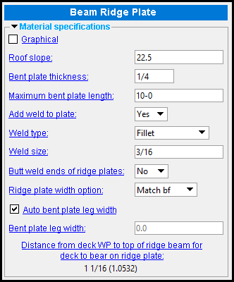
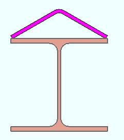
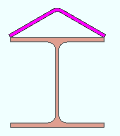
Roof slope: The number of degrees that each leg of the ridge plate is bent from horizontal. The slope you enter here changes the pitch of the ridge plate so that it matches the value that you enter. The number of degrees entered here equals half the " Bend angle " that is reported on the Bent Plate Material window.
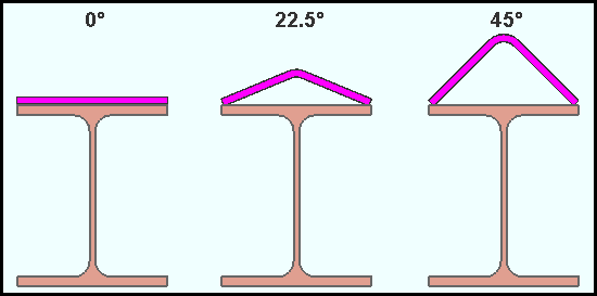
' 0 ' degrees flattens the ridge plate against the top flange of the ridge beam. The ridge plate has no bend.
' 22.5 ' makes each leg of the ridge plate slope 22.5 degrees upward and inward, toward the center of the beam.
' 45 ' makes each leg of the ridge plate slope 45 degrees.
Bent plate thickness: 3/16 or 1/4 or 3/8 or 1/2 . Each of these four thicknesses are fractions of an inch. They set the " Material thickness " of the bent plate material that the ridge plate is made of. On the Bent Plate Material window, the thickness that you select here will be expressed in the primary dimension " Units ."
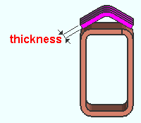
|
The thickness dimension of a ridge plate that was added to an HSS/TS beam. |
Maximum bent plate length: A distance (in the primary dimension " Units " or other units ).
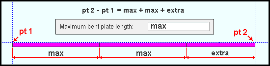
When the two end points of the ridge plate is greater than the " Maximum bent plate length ," the bent plate that makes up the ridge plate is divided into segments. All segments except the segment closest to point 2 are each the " Maximum bent plate length ." The segment closest to point 2 is whatever extra length is left over. Point 1 and point 2 are established when the ridge plate is added .
Add weld to plate: Yes or No .
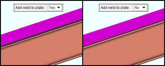
' Yes ' welds the ridge plate to the top flange of the beam.
' No ' stops the beam ridge plate component from welding the ridge plate to the top flange of the beam. .
Weld type: Fillet or Square groove . This applies when " Add weld to plate " is set to ' Yes '. It sets the weld " Type " on the Weld Edit window in Modeling as well as the weld " Type " for the weld symbol on the beam detail.
| symbol | name | weld used for... |
|
|
fillet | General welding of material. |
|
|
square groove | Butt joints of material 3/8" thick or less. |
Weld size: A distance (in the primary dimension " Units " or other units ) that indicates depth of preparation, size or strength of the weld. This sets the " Weld size " on the Weld Edit window in Modeling as well as the " Weld size " for the weld symbol on the beam detail.
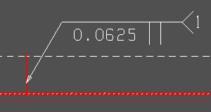
Butt weld ends of ridge plates ( if applicable ): Yes or No . This can apply when the ridge plate has been divided into multiple segments due to the " Maximum bent plate length " being less than the distance between the end points of the ridge plate.
|
A butt weld symbol designating a joint between segments of a ridge plate. The gap between segments is 1/6 inch (0.0625 inch). |
' Yes ' butt welds the segments to the ridge plate.
' No ' stops the beam ridge plate component from butt welding segments of the ridge plate.
Ridge plate width option: Match bf or Match toes . The following example shows the results obtained when " ![]() Auto bent plate leg width " is checked.
Auto bent plate leg width " is checked.
|
' Match bf ' sets the width of the ridge plate to match the width of the beam flange when "
' Match toes ' sets the width of the ridge plate to be slightly larger than does ' Match bf '. When "
Auto bent plate leg width: ![]() or
or ![]() .
.
|
In this example , " |
|
Same as above , except that " |
If this box is checked (
If the box is not checked (
), then " Bent plate leg width " becomes enabled (no longer read-only). To that entry field, you can enter a width of your own choosing.
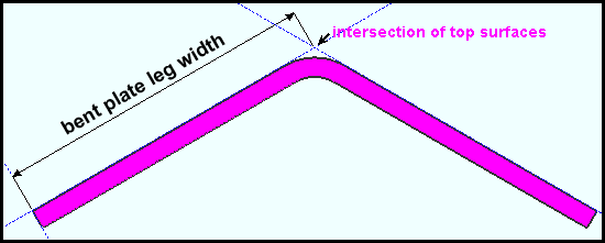
Bent plate leg width: The distance (in the primary dimension " Units " or other units ) from the edge of the leg to the projected intersection of the top surfaces of the legs. This projected leg intellection point lies above the actual, physical apex of the bent plate -- it is not a point on the material. Both legs of the bent plate are this same " Bent plate leg width ." To change the leg width, " ![]() Auto bent plate leg width " needs to be turned off (not checked).
Auto bent plate leg width " needs to be turned off (not checked).
Warning : Entering a " Bent plate leg width " that is greater than the "
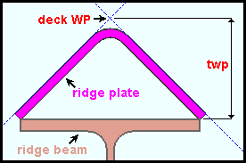
Distance from deck WP to top of ridge beam for deck to bear on ridge plate: read-only .
|
twp is the distance from the deck WP to the top of the ridge beam. The deck WP is the projected intersection of the top surfaces of the legs of the ridge plate. This deck WP lies above the actual, physical apex of the ridge plate -- it is not a point on the ridge plate material |
The distance that is reported here updates when you change the " Roof slope " or the " Bent plate thickness " or the " Bent plate width option ." It will also change if you change the beam " Section size ."

