 Add Column Stiffeners - Column ( Modeling )
Tool summary :
-
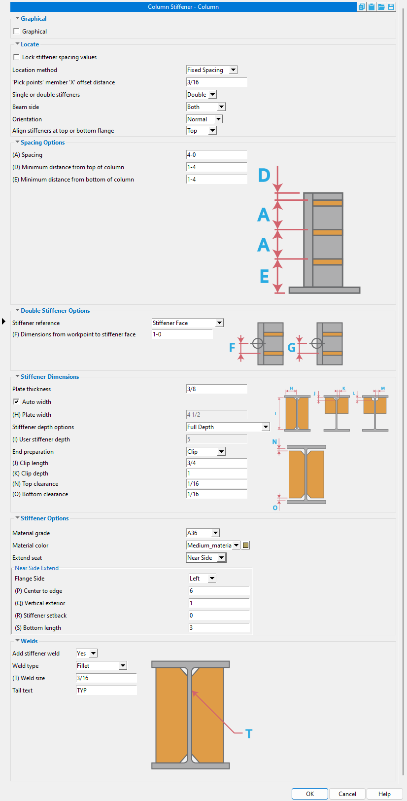
Location Method: Fixed Spacing
-
Orientation: Normal
-
Stiffener reference: Stiffener Face
-
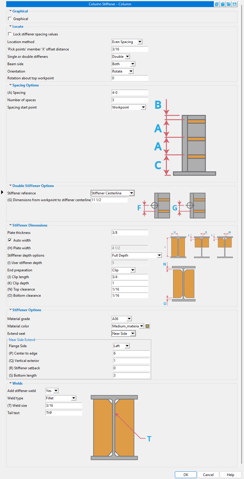
Location Method: Even Spacing
-
Orientation: Rotate
-
Stiffener reference: Stiffener Centerline
You can click the Add Column Stiffeners - Column icon instead of doing steps 2 and 3 of the procedure that follows. The icon can be found in the command group ' Model--Component ' for the Ribbon Editor.
- Preselection method of adding: 1 ) In Modeling , select a flanged column. 2 ) Invoke Add Component . 3 ) On the custom component selection list, choose " Column Stiffeners - Column ." 4 ) The Column Stiffeners - Column window opens so that you can configure the sizing and placement of the stiffeners to suit your purposes ...
- If you use in-tool selection -- that is, select the column after activating this tool or after selecting " Column Stiffener at Beam " as the component you want to add -- only columns will be selectable. Select a column with flanges. For example, select a wide flange column.
- See the videos (
 )
)
Also see :
- Modeling (where custom components can be added)
- Custom components (topic)
- Column (member type that Column Stiffeners - Column can be added to)
- Model > Component > Add (step-by-step instructions)
Videos :
|
|
![]() Graphical -------------------------------------------------------------
Graphical -------------------------------------------------------------
Graphical : ![]() or
or ![]() .
.
|
- A Column Stiffeners - Column component is automatically set to "
 Graphical " whenever you make graphical changes to any of its materials. For example, when you Edit Material or perform a material cutting operation on a Column Stiffeners - Column material. This stops the component from being changed.
- Instead of allowing the component to be made " Graphical ." you may wish to Explode Component .
![]() Locate ------------------------------------------------------------------
Locate ------------------------------------------------------------------
Lock stiffener spacing values: ![]() or
or ![]() .
.
|
" |
If this box is checked (
If the box is not checked (
), the " Location method " can be manually changed.
Location method: Pick Points or Fixed Spacing or Even Spacing .
' Pick Points ' lets you select the points along the column workline where you want the stiffeners. You can Navigate > Snap To Surface on the column web to create a suitable view. You may also want to lay out construction lines so that there are INCL or INCM points where you want the stiffeners. See " Pick points' member 'X' offset distance ."
' Fixed Spacing ' gives you options for setting the " Minimum distance from top of column " to the bottom stiffener, and the " Minimum distance from top end of column " to the top stiffener. The " Spacing " between the stiffeners is fixed at the user-entered distance. A maximum number of stiffeners will be generated (at the fixed spacing) to fill the available space.
' Even Spacing ' creates even spacing between the " Number of spaces " you enter. The spacing will be across the columns's " WP to WP length, actual " when ' Workpoint ' is selected as the " Spacing start point ." It will be spaced across the length of the column main material when ' Minus Dimension ' is selected as the " Spacing start point ."
'Pick points' member 'X' offset distance: A positive (+) or negative (-) distance (in the primary dimension " Units " or other units ). This applies when the " Location method " is ' Pick Points '. The offset adjusts the stiffeners' placement with respect to the points that you locate.
Single or double stiffeners: Single or Double .
|
To place the stiffeners shown here, the " Location method " was set to ' Pick points ' and INCM points were located. The middle column has " Single or double stiffeners " set to ' Single '. The Right column has " Single or double stiffeners " set to ' Double '. |
' Single ' places a single stiffener (or a pair of near-side and far-side stiffeners) at the spacing that is based on the " Location method " that is selected.
' Double ' places twice as many stiffeners, evenly spaced between the spacing that is set per the selected " Location method ." See " Double stiffener options ."
Column side: Near Side or Both or Far Side .
|
|
|
|
The view is from above the top end of a column.
|
||
' Near Side ' places the stiffeners on the near side of the column's web. If you are looking at the top of a column whose " Column rotation " is ' 0 ', the near side of the column's web is below the web.
' Both ' places the stiffeners on both the near side and far side of the column.
' Far Side ' places the stiffeners on the far side of the column's web.
Orientation: Normal or Horizontal or Rotate .
' Normal ' orients the stiffeners normal to the column. That is, the stiffeners will be perpendicular to the column's flanges.
' Horizontal ' orients the stiffeners horizontally.
' Rotate ' lets you, the user, specify the rotation of the stiffeners by entering a number of degrees for the " Rotation about top workpoint . "
Note: On a perfectly vertical column, ' Normal ' and ' Horizontal ' produce the exact same result.
Rotation about workpoint: A positive (+) or negative (-) number of degrees . This rotation can be applied when the " Orientation " is set to ' Rotate '.
' 0 ' degrees positions the stiffeners normal to the column's flanges.
A positive number of degrees rotates the stiffeners clockwise around the stiffener's workpoint on what is the column's left flange when you are looking at the near side of the column.
A negative number of degrees rotates the stiffeners counterclockwise around the stiffener's workpoint on what is the column's left flange when you are looking at the near side of the column.
![]() Fixed Options --------------------------------------------------------------
Fixed Options --------------------------------------------------------------
Minimum distance from top of column: A distance (in the primary dimension " Units " or other units ). This applies when the " Location method " is ' Fixed Spacing '. The top stiffener will be placed at least this distance away from the top-end workpoint of the column. The " Minimum distance ... " is measured to the centerline of the stiffener.
|
Since the " Minimum distance from top of column " is ' 8 ' inches, the top stiffener is placed 8 inches or farther away from the top of the column material. In this example, it is placed 1 foot away from the top of the material. |
Minimum distance from bottom of column: A distance (in the primary dimension " Units " or other units ). This applies when the " Location method " is ' Fixed Spacing '. The bottom stiffener will be at least this distance away from the top of the column.
|
|
Since the " Minimum distance from bottom of column " is ' 8 ' inches, the bottom stiffener is placed 8 inches or farther away from the bottom of the column material. In this example, it is placed 1 foot away from the bottom of the material. |
Spacing: A distance (in the primary dimension " Units " or other units ). The spacing is measured from the center of one stiffener to the next. It applies when the " Location method " is ' Fixed Spacing ' or ' Even Spacing ', but you can change this spacing only for fixed spacing. Changes made to even spacing may be recalculated and overwritten when you press " OK . " Also be aware that you cannot change this spacing when " Lock stiffener spacing values " is checked.
|
|
This example shows a 5'-0" foot column. Since the " Minimum distance ... " for each end is ' 8 ' inches, that leaves a maximum of 3'-8" of available space for the stiffeners. Since the stiffeners are set to have a " Spacing " of ' 1-6 ', three stiffeners (with two 1'-6" spaces between them) are able to fill the available space. |
Number of spaces: The number ( a count ) of spaces. This applies when the " Location method " is ' Even Spacing '. The spaces are counted differently if the " Spacing start point " is ' Workpoint ' or ' Minus dimension ' as opposed to ' Dimension '.
If " Spacing start point " is ' Workpoint ' or ' Minus Dimension ', this count is the spacing between stiffeners plus 2. The 2 added spaces are: 1 ) The space from the bottom end of the column to the bottom stiffener. 2 ) The space from the top end of the column to the top stiffener.
If " Spacing start point " is ' Dimension ', this count is the spacing between stiffeners only. The count does not include the distances from the ends of the column to the outermost stiffeners since those values are defined by the " Distance from top end to first stiffener " and " Distance from bottom end to first stiffener ."
Spacing start point: Workpoint or Minus Dimension or Dimension . The starting point when the " Location method " is ' Even Spacing '.
'Workpoint' or 'Minus Dimension' defines where the space from the end of the column to the nearest stiffener is measured from. If ' Workpoint ' is selected, the two outermost spaces are measured from the bottom/top workpoint to the nearest stiffener. If ' Minus Dimension ' is selected, the two outermost spaces are measured from the bottom/top end of the main material to the nearest stiffener.
|
|
' Dimension ' gives you options for " Distance from bottom end to first stiffener " and " Distance from top end to first stiffener ," which are measured from the bottom and top end workpoints of the column.
Distance from bottom end to first stiffener
and
Distance from top end to first stiffener: A distance (in the primary dimension " Units " or other units ) from the bottom/top column workpoint to the stiffener that is nearest to that end. These settings apply when " Spacing starting point " is set to ' Dimension '.
In this example of ' Even Spacing ', the " Number of spaces " is ' 3 ' and the " Spacing start point " is set to ' Dimension '. Each space is automatically calculated to evenly fill up the available space between the user-entered dimensions from the bottom/top ends ( bttm and top ). The automatically calculated even spacing between stiffeners is represented in this example as the value x.
![]() Double Stiffener Options -----------------------------------------------------------
Double Stiffener Options -----------------------------------------------------------
Stiffener reference: Stiffener Face or Stiffener Centerline . This applies when ' Double ' stiffeners are selected.
' Stiffener Face ' gives you an option to " Dimension from workpoint to stiffener face ."
' Stiffener Centerline ' gives you an option to " Dimension from workpoint to stiffener centerline ."
Dimension from workpoint to stiffener face: The distance (in the primary dimension " Units " or other units ) from each double stiffener workpoint location to the nearest face of each of the two stiffeners (the ' Double ' stiffeners). This applies when " Stiffener reference " is set to ' Stiffener Face ', which applies when ' Double ' stiffeners are selected.
Dimension from workpoint to stiffener centerline: The distance (in the primary dimension " Units " or other units ) from each double stiffener workpoint location to the centerline of each of the two stiffeners (the ' Double ' stiffeners). This applies when " Stiffener reference " is set to ' Stiffener Centerline ', which applies when ' Double ' stiffeners are selected.
![]() Stiffener Dimensions ---------------------------------------------------------------
Stiffener Dimensions ---------------------------------------------------------------
Plate thickness: A distance (in the primary dimension " Units " or other units ). This distance will be The " Material thickness " of the rectangular plate material that the column stiffeners are made of.
|
The calculated auto width of the stiffener sets the " Material width " of the rectangular plate that the stiffener is made from. |
If this box is checked (
If the box is not checked (
Plate width: A distance (in the primary dimension " Units " or other units ). This applies when " ![]() Auto width " is not checked.
Auto width " is not checked.
|
|
The " Plate width " entered here is made the " Material width " of the stiffener when " |
Stiffener depth options: Full Depth or Top Flange Half Depth or Bottom Flange Half Depth or Top Flange Bottom K or Bottom Flange Top K or Top Flange User Depth or Bottom Flange User Depth . The stiffeners will be sized automatically based on the " Depth " specified for the column's section size in the local shape file .
|
When the " Column rotation " is ' 0 ', the column's top flange is its left flange in a plan view. |
' Full Depth ' extends each stiffener to the inside surfaces of the top and bottom flanges of the column.
' Top Flange Half Depth ' extends the top edge of each stiffener to the inside surface of the top flange of the column and the bottom edge of each stiffener to the half-depth of the column.
' Bottom Flange Half Depth ' extends the bottom edge of each stiffener to the inside surface of the bottom flange of the column and the top edge of each stiffener to the half-depth of the column.
' Top Flange Bottom k ' extends the top edge of each stiffener to the inside surface of the top flange of the column and the bottom edge of each stiffener to the k distance from the outside surface of the column's bottom flange.
' Bottom Flange Top k ' extends the bottom edge of each stiffener to the inside surface of the bottom flange of the column and the top edge of each stiffener to the k distance from the outside surface of the column's top flange.
' Top Flange User Depth ' extends the top edge of each stiffener to the inside surface of the top flange of the column and the bottom edge of each stiffener to the " User stiffener depth " from the stiffener's top edge.
' Bottom Flange User Depth ' extends the bottom edge of each stiffener to the inside surface of the bottom flange of the column and the top edge of each stiffener to the " User stiffener depth " from the stiffener's bottom edge.
User stiffener depth: A distance (in the primary dimension " Units " or other units ). When " Stiffener depth options " is set to ' Top Flange User Depth ' or ' Bottom Flange User Depth ', the value that is entered here is the depth of the stiffener plates. On the Rectangular Plate Material window, this will be the " Order length " of each of the plates.
End preparation: Clip or Cope or Exact Fit .
' Clip ' gives you options for entering a " Clip depth " and a " Clip length ." See the illustration above.
' Cope ' gives you options for entering a " Cope depth " and " Cope length ." See the illustration above.
' Exact Fit ' exactly cuts the plate to the profile of the column with a 1/16 inch clearance.
Top clearance: The distance (in the primary dimension " Units " or other units ) from the top edge of each stiffener and the inside surface of the top flange of the column.
|
When the " Column rotation " is ' 0 ', the column's top flange is its left flange in a plan view. |
Bottom clearance: The distance (in the primary dimension " Units " or other units ) from the bottom edge of each stiffener and the inside surface of the bottom flange of the column.
|
|
When the " Column rotation " is ' 0 ', the column's bottom flange is its right flange in a plan view. |
![]() Stiffener Options ---------------------------------------------------------------
Stiffener Options ---------------------------------------------------------------
Material grade: A36 or A572 or etc. This is the grade of steel for the stiffeners. This is also the " Steel grade " of the rectangular plate material that each stiffener is made of.
Setup: If the grade of steel you want is not shown on the list box (
), you can use Home > Project Settings > Job > Plate Grades to add it to the list.
Material color: A predefined color or a custom color . This is the approximate color of the stiffener plates when the column they are submaterials of is displayed in one of the three solid forms . This is also the " Color " of the rectangular plate material that a stiffener is made of.
The predefined colors are set up on the Predefined Colors window. The color swatch next to the list box (
Select ' Custom Color ' (last choice on the list) to launch your operating system's color picker and define any color you like.
Extend seat: None or Near Side or Far Side or Both .
|
| The " Column rotation " of these columns is ' 0 '. The columns are in a plan view. |
' None ' keeps the stiffeners unextended.
' Near Side ' adds an extend seat to the near side of the column and extends the near side stiffeners to the seat based on the choices that you make to " Flange side ," " Center to edge ," " Vertical exterior ," " Stiffener Setback " and " Bottom length ."
' Far Side ' gives the same results as ' Near Side ', but for the stiffeners on the far side of the column.
' Both ' adds extend seats to both the near side and far side of the column and extends the stiffeners on those sides to them.
Flange side: Left or Right . This sets the flange that is extended when " Extend seat " is set to ' Near Side ' or ' Far Side ' or ' Both '.
|
The " Column rotation " of all six of these columns is ' 0 '. The columns are in a plan view. Consequently, the left flange is to your left, and the right flange is to your right. |
|
|
' Left ' is the flange that is to your left in a plan view when the " Column rotation " is ' 0 '.
' Right ' is the flange that is to your right in a plan view when the " Column rotation " is ' 0 '.
Center to edge: The distance (in the primary dimension " Units " or other units ) from the center of the column web to the furthest edge of the seat. This distance must be greater than half the flange width (bf) of the column. The " Material width " of the seat is the " Center to edge " distance entered here minus half the flange width (bf) of the column. The " Center to edge " option applies when " Extend seat " has been set to ' Near Side ' or ' Far Side ' or ' Both '.
Vertical exterior: A distance (in the primary dimension " Units " or other units ). This is the length of the outside edge of the stiffener plate. The " Vertical exterior " option applies when " Extend seat " has been set to ' Near Side ' or ' Far Side ' or ' Both '.
Stiffener setback: The distance (in the primary dimension " Units " or other units ) that the outside edge of the stiffener plate is to be set back from the outside edge of the seat. If a distance of ' 0 ' is entered, the outside vertical edge of the stiffener plate will go all the way to the outside edge of the seat. The " Stiffener setback " option applies when " Extend seat " has been set to ' Near Side ' or ' Far Side ' or ' Both '.
Bottom length: The distance (in the primary dimension " Units " or other units ) of the bottom edge of the stiffener plate that is parallel to and welds to the inside face of the bottom flange of the column. The " Bottom length " option applies when " Extend seat " has been set to ' Near Side ' or ' Far Side ' or ' Both '.
![]() Welds ----------------------------------------------------------------------------------
Welds ----------------------------------------------------------------------------------
Add stiffener weld: Yes or No .
' Yes ' shop welds the stiffeners to the column.
' No ' instructs the Column Stiffeners - Column custom component to not add welds.
Weld type: Fillet or Square groove or Bevel groove . This sets the " Weld type " on the Weld Edit window in Modeling as well as the " Weld type " for the weld symbol on the column detail.
| symbol | name | weld used for... |
|
|
fillet | General welding of material. |
|
|
square groove | Butt joints of material 3/8" thick or less. |
|
|
bevel groove | General full penetration welding of material. |
Weld size: A distance (in the primary dimension " Units " or other units ) that indicates depth of preparation, size or strength of the weld. This sets the " Weld size " on the Weld Edit window in Modeling as well as the " Weld size " for the weld symbol on the column detail.
Tail text: blank or a text string . This sets the " Supplementary tail text " on the Weld Edit window in Modeling as well as the " Supplementary tail text " for the weld symbol on the column detail.
|
The text string " TYP " is the tail text for this weld symbol. |
If this field is left ' blank ', a tail is not drawn on the weld symbol.
If a ' text string ' is entered, a tail with that character string as the tail text is drawn on the weld symbol.

