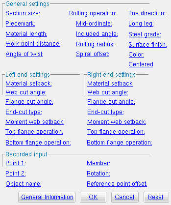
The Parametric Rolled Section Material window
| Quick Notes |
Options :
General information :
Also see :
- Parametric Point Maps
- Objects, Attributes, Methods and Functions
- Rolled Section Material (similar window - for Modeling )
- Wide flange (a type of rolled section)
- Channel (a type of rolled section)
- Angle (a type of rolled section)
- HSS round (pipe) (a type of rolled section)
- HSS rectangular (tube) (a type of rolled section)
- W tee (a type of rolled section)
Warning : If your startup code specifies imperial Units("...") , make entries to distance fields on this window in decimal inches, not fractions. Also, do not use hyphens ( - ). If you enter a fraction using integers, Python truncates the results of the division operation to an integer (examples: 1/8 = 0 ; 5/4 = 1 ). If you enter fractions with decimal points, Python calculates the precise decimal value (examples: 1.0/8.0 = .125 ; 5.0/4.0 = 1.25 ). If you enter a hyphen, Python interprets the hyphen as a minus sign (examples: 1-2 = -1 ; 3-2 = 1 ). See numbers (floating point numbers and integers).
To enter a dimension string and convert it to a floating point distance that is properly factored based on the startup code
Units("..."), you can use thedim("...")function. See the warning above for an explanation of why thedim()function is needed.
------ General settings ------
Section size ( obj . SectionSize or obj.section_size ): Any W , L , C , HSS round , HSS rectangular or WT section size that is listed in the local shape file . If the box for " String " is checked ( ![]() ), validation requires that your entry be a section size that is listed in the local shape file. If the box for " String " is not checked (
), validation requires that your entry be a section size that is listed in the local shape file. If the box for " String " is not checked ( ![]() ), validation lets you enter a variable that will return a string from the local shape file.
), validation lets you enter a variable that will return a string from the local shape file.
To enter a section size: With " String " checked (
), you can type in the section size that you want, or press the "file cabinet" browse button (
) and double-click any section that is on the list of available materials in the local shape file . For example, if you enter L6x4x3/8 , the resulting line of parametric code reads:
obj.SectionSize = "L6x4x3/8"(whereobjis the " Object name "). Note from this example that you do not have to put the section size in quotes.To enter a variable : With " String " not checked (
), you can enter a variable that will return a string that is the section size of a material or member previously defined in the code. For example, you could enter
mem1.SectionSizeto get the section size of a previously named member object calledmem1. In the parametric code, the variable will not be in quotes, since the variable itself is not a string, though it returns a string.Example: Suppose you are creating a Python script for welding a pair of double clip angles and that the first angle has the " Object name " of
ang1and this angle isang2. If you wanted this angle to be assigned the same section size asang1, you could set "ang1.SectionSize. The resulting line of parametric code would read:ang2.SectionSize = ang1.SectionSize.
Piecemark: You can add a line of code such as obj.MinorMark = "xxx" or obj.Piecemark = "xxx" in a text editor.
For submaterials ( obj .MinorMark or obj.mark ):
If you Run a script that does not include
obj.MinorMark, SDS2 piecemarking looks for materials in the current Job that are physically identical to this material and assigns to this material the same submaterial mark assigned to those materials. If no matching materials are found, piecemarking assigns this material a submaterial mark using the appropriate piecemark prefix listed in Home > Project Settings > Fabricator > Member and Material Piecemarking > the " Prefixes " tab.If you Run a script with
obj.MinorMark = "xxx", SDS2 applies that submaterial mark (xxx) to the parametrically added material if no other material has yet been assigned that mark. It also applies that mark (xxx) if other materials that have that mark (xxx) are exactly like the parametrically added material. If the model contains materials with a different submaterial mark (yyy) that are exactly like the parametrically added material, the submaterial mark of those materials (yyy) is re-named to that of the parametrically added material (xxx). If the model contains materials with the same submaterial mark that the script designates to be assigned to the parametrically added material (xxx) and those materials are different than the parametrically added material, the submaterial mark in the script is not applied -- instead you get a warning and the parametrically added material is assigned a different submaterial mark using the appropriate piecemark prefix listed in Home > Project Settings > Fabricator > Member and Material Piecemarking > the " Prefixes " tab.
For miscellaneous members ( obj . Piecemark or obj.piecemark ):
If you Run a script that does not include an
obj.Piecemark, SDS2 piecemarking assigns a system piecemark to the parametrically added member during Create Solids .If you Run a script with an
obj.Piecemark, be careful. You are responsible for ensuring that members that have been assigned the same user piecemark are physically the same. SDS2 does not do this for you.Tip 1: A Python script can read the submaterial mark of a material as shown in the following example.
# Prints the piecemark of the material the user selects.
from mtrl_list import MtrlLocate
mtrl1 = MtrlLocate("Select material", "Single")
print("The material piecemark is: ", mtrl1.MinorMark)
Tip 2: A script can also read member piecemarks (user or system).
# Prints the piecemark of the member that the user selects.
from member import MemberLocate
from param import ClearSelection
mem1 = MemberLocate("Select a member")
print("The piecemark is: ", mem1.Piecemark)
ClearSelection()
Material length ( obj .OrderLength or obj.length ): The distance from the furthest point on the material's left end to the furthest point on the material's right end. A distance is a floating point number in mm or inches, depending on the startup code Units('...') . This distance is measured parallel with the material's longitudinal axis ( X material axis ).
Example 1: Entering a specific dimension results in the length of the material being that set value when this script is Run.
Example 2: Entering
obj.WorkpointSlopeDistance - obj.MaterialSetbackLeftEnd - obj.MaterialSetbackRightEnd(whereobjis the " Object name ") calculates the length of the material by subtracting the " Left & right material setback " from the " Work point distance ." The resulting line of parametric code reads:obj.OrderLength = obj.WorkpointSlopeDistance - obj.MaterialSetbackLeftEnd - obj.MaterialSetbackRightEnd.
Work point distance ( obj .WorkpointSlopeDistance or obj.work_pt_dist ): The distance between " Point 1 " and " Point 2 " (see step 3 ). A distance is a in mm or inches, depending on the startup code Units('...') .
Example 1: Entering
obj.Point1.Distance(obj1.Point2)whereobjis the " Object name " causes the work point distance to be calculated from the global coordinates of the two work points (" Point 1 " and " Point 2 "). The resulting line of parametric code reads:obj.WorkpointSlopeDistance = obj.Point1.Distance(obj1.Point2).
Angle of twist ( obj .MaterialTwistAngle or obj.angle_of_twist ): 0 degrees or the positive or negative (-) number ( floating point number ) of degrees of twist about the longitudinal axis ( X material axis ) of the rolled section. This axis is defined by the workline of the rolled section (see step 3 ).
Entering 0 (zero) results in the material created when this script is Run or Tested not being twisted. The resulting line of parametric code reads:
obj.MaterialTwistAngle = 0.000000(whereobjis the " Object name ").Entering a specific
number.decimal( floating point number ) of degrees causes " Point 1 " of the material to remain fixed, while the right end is rotated the number of degrees entered. Validation accepts entries between -3600.0 and 3600.0 degrees and can generate twists to .06 degree. Assuming you are looking from the right end toward the left end of the material, a positive entry rotates the material counterclockwise.
Rolling operation ( obj .RollType or obj.rolling_op ): "None" or "Camber" or "Weak Axis" or "Strong Axis" . The center of curvature for any of these choices (except "None" ) is midway between the left and right ends of the rolled section. In the parametric code, the choice you make is designated with a string ( "None" or "Camber" or "Weak Axis" or "Strong Axis" ).
"None" 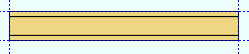 |
"Camber" 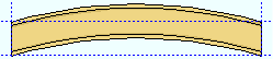 |
"Weak Axis" 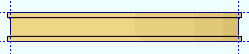 |
"Strong Axis" 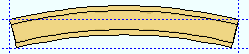 |
"None"makes the rolled section straight (not curved). The resulting line of parametric code reads:obj.RollType = "None"(whereobjis the " Object name ").
"Camber"produces parabolic bending along the strong axis of the rolled section with the ends fixed. The " Mid-ordinate " sets the offset at mid-span and the direction (+ or -) of that offset.
"Weak Axis"or"Strong Axis"produces rolling that is circular. The " Mid-ordinate " or " Included Angle " or " Rolling radius " sets the offset at mid-span and the direction (+ or -) of that offset. For " Strong Axis " or " Weak Axis " rolling, the two ends of the rolled section are not fixed; that is, if the ends were vertical before the operation they may not be vertical afterwards.
Mid-ordinate ( obj .MidOrdinate or obj.mid_ordinate ): A positive or negative (-) distance ( floating point number ) in mm or inches, depending on the startup code Units('...') . This distance is the rolled section's offset at mid-span as a result of a " Rolling operation " of " Camber " or " Strong Axis " or " Weak Axis ". The sign (+ or -) sets the direction of offset.
Strong axis rolling with a positive mid-ordinate ( +m ) 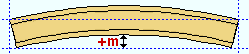 |
Strong axis rolling with a negative mid-ordinate ( -m ) 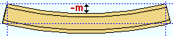 |
| Weak axis rolling with a positive mid-ordinate ( rolling toward the near side ) |
Weak axis rolling with a negative mid-ordinate ( rolling toward the far side ) 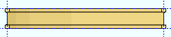 |
Camber with a positive mid-ordinate ( +m ) 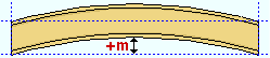 |
Camber with a negative mid-ordinate ( -m ) 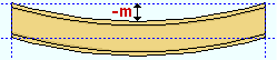 |
Example: You enter
5.0here. The resulting line of parametric code reads:obj.MidOrdinate = 5.0(whereobjis the Object name ).
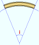
Included angle ( obj .IncludedAngle or obj.bend_angle ): The positive or negative (-) number ( floating point number ) of degrees that sets the angle of curvature when " Strong axis " or " Weak axis " is the " Rolling operation ."
|
i = included angle. Extrapolate a circle from the inside curvature of the material, then draw a line along each end of the material. The lines will meet at the center of the imaginary circle, and their included angle is the angle entered here. |
Example: You enter
10.0here. The resulting line of parametric code reads:obj.IncludedAngle = 10.0(whereobjis the Object name ).
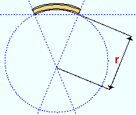
Rolling radius ( obj .RollingRadius or obj.bend_radius ): A positive or negative (-) distance ( floating point number ) in mm or inches, depending on the startup code Units('...') . This distance defines the amount of curvature of the rolled section when " Strong Axis " or " Weak Axis " is the " Rolling operation ."
|
r = rolling radius. If you were to extrapolate a circle from the inside curvature of the material, the distance from any point on the inside curve of the top/bottom flange to the center of the circle is the distance entered here. |
Example: You enter 100.0 here. The resulting line of parametric code reads:
obj.RollingRadius = 100.0(whereobjis the Object name ).
Spiral offset ( obj .SpiralOffset or obj.rolled_offset ): A positive or negative (-) distance ( floating point number ) in mm or inches, depending on the startup code Units('...') . This is the distance that the right end of the rolled section is to be offset from " Point 2 " when Weak axis or Strong axis is the " Rolling operation ."
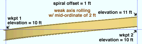
For a rolled section input in a plan view : A positive distance raises the elevation with respect to " Point 2 "; a negative (-) distance lowers the elevation with respect to " Point 2 ."
Example: You enter
100.0to this field. The resulting line of parametric code reads:obj.SpiralOffset = 100.0(whereobjis the " Object name ").
Toe direction ( obj .ToeInOrOut or obj.toe_io ): "In" or "Out" . This applies to channel and angle materials. The choice you make here results in the entry of a string ( "In" or "Out" ) to the parametric code.
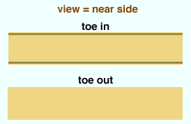
"In" results in a line of parametric code reads:
obj.ToeInOrOut = "In"(whereobjis the " Object name "). When facing the near side of the channel or angle (the near side is the side where the material's " Point 1 " is to your left), the flange(s) point toward you."Out" results in a line of parametric code reads:
obj.ToeInOrOut = "Out"(whereobjis the " Object name "). The flange(s) of the angle or channel point away from you if you are looking at the material's near side.
Long leg ( obj .IsLongLegVerticalMaterial or obj.llv ): "HZ." or "VT." . This applies to angles with legs of unequal length. The choice you make here results in the entry of a string ( "HZ." or "VT." ) to the parametric code.
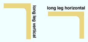
"HZ." specifies that long leg of the angle is horizontal. The resulting line of parametric code reads:
obj.IsLongLegVerticalMaterial = "HZ."(whereobjis the " Object name ")."VT." specifies that long leg of the angle be vertical. The resulting line of parametric code reads:
obj.IsLongLegVerticalMaterial = "VT."(whereobjis the " Object name ").
Steel grade ( obj .MaterialGrade or obj.grade ): Any steel grade ( "A36" or "A572" or etc.) from the list of Wide Flange Grades or WT Grades or Channel Grades or Angle Grades or Pipe Grades or HSS / TS Grades can be selected on the list box ( ![]() ) for this field.
) for this field.
Example: You select A36 here. The resulting line of parametric code reads:
obj.MaterialGrade = "A36"(whereobjis the " Object name " and "A36" is a string from one of the aforementioned setup tables).
Surface finish ( obj .SurfaceFinish or obj.finish ): "None" or "Sand Blasted" or "Red Oxide" or "Yellow Zinc" or "Gray Oxide" or "Blued Steel" or "Galvanized" can be selected on the list box ( ![]() ) for this field. The choice you make here assigns the selected string as the
) for this field. The choice you make here assigns the selected string as the SurfaceFinish attribute for this " Object name " in the parametric code.
|
||||||
| The colors of materials on Drawing Editor erection views in ' Solid ' or ' Stick + solid ' are set per their surface finish. |
Example: Selecting Yellow Zinc results in a line of parametric code that reads:
obj.SurfaceFinish = "Yellow Zinc"(whereobjis the " Object name ").Also note: When you export a KISS file using Model as the " Data source ," surface finish data on materials are compiled into the P lines in the KISS download. Surface finish data can also be output to a fabtrol_assembly_parts_list.XSR file.
Color ( obj .MaterialColor3d or obj.color ): A >"named_color" or a custom color . The choice you make here assigns three values (RGB values) from 0 to 255, which define the color of the rolled section when it is displayed in one of the three solid forms .
The
named_colorsare set up on the Predefined Colors window. The color swatch next to each predefined color on the menu () shows you the color that the material will be when you look at it straight on in solid opaque form. Example: Selecting
Medium_beamresults in a line of parametric code that reads:obj.MaterialColor3d = "Medium_beam"(whereobjis the " Object name ").Select Custom Color (last option on the menu) to launch your operating system's color picker and define any color you like. Example: Selecting a custom color results in a line of parametric code that reads:
obj.MaterialColor3d = (r, g, b)whererorgorbis an integer value from 0 to 255 andobjis the " Object name ."
Centered ( obj .Centered or obj.centered ): ![]() or
or ![]() ( "Yes" or "No" ). The choice you make here results in the entry of a string ( "Yes" or "No" ) to the parametric code.
( "Yes" or "No" ). The choice you make here results in the entry of a string ( "Yes" or "No" ) to the parametric code.
| Centered, origin at left end : |
|
| Not centered, origin at left end : |
|
| Not centered, origin at right end : |
|
If this box is checked (
obj.Centered = "Yes"(whereobjis the " Object name ").If the box is not checked (
obj.Centered = "No"(whereobjis the " Object name ").
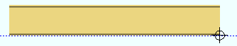
------ Left end settings ------ | ------ Right end settings ------
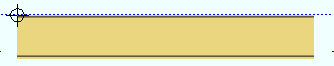
| Tip : The left end is the " Point 1 " end of this material. |
Material setback ( obj .MaterialSetbackLeftEnd or obj .MaterialSetbackRightEnd ): A positive or negative (-) distance ( floating point number ) in mm or inches, depending on the startup code Units('...') . This is the distance that the (left or right) end of the rolled section is to be displaced from its work point.
A positive distance entered here brings the (left or right) end of the rolled section back in toward the opposite end of the material from " Point 1 " (for left setback) or " Point 2 " (for right setback) when " Material length " is calculated using the expression
obj.WorkpointSlopeDistance - obj.MaterialSetbackLeftEnd - obj.MaterialSetbackRightEnd.Entering
0under " Left end settings " gives you parametric code that reads:obj.MaterialSetbackLeftEnd = 0.000000(whereobjis the " Object name "). If0is entered for this field under " Right end settings ," the resulting parametric code reads:obj.MaterialSetbackRightEnd = 0.000000.
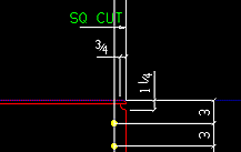
Web cut angle ( obj .WebCutLeftEnd or obj .WebCutRightEnd ): A positive or negative (-) angle ( floating point number ) from 89 to -89 degrees. Angles closer to zero than .057 degrees are rounded to zero when the material is created.
An entry of
0(zero) designates that no web cut be made. Assuming that the left end of the web is to your left on screen: a positive angle is measured counterclockwise from a perpendicular bisector to the workline; a negative (-) angle is measured clockwise from a perpendicular bisector to the workline.
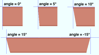
Flange cut angle ( obj .FlangeCutLeftEnd or obj .FlangeCutRightEnd ): A positive or negative (-) angle ( floating point number ) from 89 to -89 degrees. This is the angle at which both the near and far side of the flange are to be cut.
An entry of
0(zero) designates that no web cut be made. Assuming that the left end of the top flange is to your left, a positive angle is measured counterclockwise from a perpendicular bisector to the flange center line. A negative (-) angle is measured clockwise from a perpendicular bisector to the top flange center line.Note: This operation functions in a different way when " Top/Bottom flange operation " is set to ' Clip flange '.
End-cut type ( obj .LeftEndPreparation or obj .RightEndPreparation ): "Standard cut" or "Square cut" or "Bevel cut" or "Mill cut" .
|
The selection made here (other than Standard cut ) is designated by an annotation on the member detail instructing how the material should be cut. If Standard cut is selected, the detail is not annotated with special cut instructions. For columns there is an option to Home > Project Settings > Fabricator > Detailing > Member Detailing Settings > the " Columns " section > " Mill cut ends of columns ." The selection made here overrides the choice made in Fabricator Setup .
Moment web setback ( obj .MomentConnectionWebSetbackLeftEnd ) or ( obj .MomentConnectionWebSetbackRightEnd ): The distance that you want the web of this material to be set back. A distance is a floating point number in mm or inches, depending on the startup code Units('...') .
This option only applies when both the " Top operation " and " Bottom operation " is set to ' Cope shop weld ' or ' Cope field weld ' or ' FEMA cope field weld ' or ' FEMA cope shop weld ' on this end and 0 has been entered as the " Cope length ."
Top/bottom flange operation ( obj .TopOperationTypeLeftEnd or ( obj .TopOperationTypeRightEnd or obj .BottomOperationTypeLeftEnd or obj .BottomOperationTypeRightEnd ): "None" or "Cope plain" or "Cope shop weld" or "Cope field weld" or "Cut flange flush" or "Clip flange" or "Notch" or "Notch NS/FS" or "FEMA cope field weld" or " FEMA cope show weld" or "Clip web" .
"None" designates that no top/bottom flange cutting operation be performed on this material.
"Cope plain" or "Cope shop weld" or "Cope field weld" designates weld preparation and/or a cut to remove part of the top/bottom flange plus part of the web. " Cope shop weld " or " Cope field weld " work best for wide flange or W tee; " Cope plain " works for all material types. Tip : A " Cope length " of 0 for " Cope shop weld " or " Cope field weld " causes weld preparation without a coping operation.
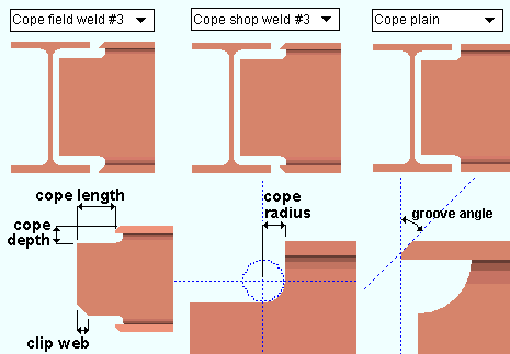
Cope length ( obj . TopLengthLeft or obj . TopLengthRight or obj . BottomLengthLeft or obj . BottomLengthRight ): 0 or the distance from the (left or right) end of the material along the material's longitudinal axis ( X material axis ).
Cope depth ( obj . TopCopeLeft or obj . TopCopeRight or obj . BottomCopeLeft or obj . BottomCopeRight ): The distance from the top of the top flange (or bottom of the bottom flange) into the web of the material.
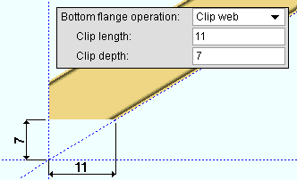
Clip web (
obj .TopWebLeftorobj .TopWebRightorobj .BottomWebLeftorobj .BottomWebRight): Applies only for " Cope shop weld "."Cut flange width" : For wide flange or W tee material (illustrated below), this option designates flange cuts on both the near side and the far side of the web. For channel or angle material, it designates a single cut (on the flange or on one leg of the angle) and you need only enter " Flange length NS " if the material is toe in, " Flange length FS " if the material is toe out.
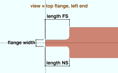
Top/Bottom flange length NS (
obj .TopLengthNSLeftorobj .TopLengthNSRightorobj .BottomLengthNSLeftorobj .BottomLengthNSRight): The distance from the (left or right) end of the material along the length of the near side of the top/bottom flange.Top/Bottom flange length FS (
obj .TopLengthFSLeftorobj .TopLengthFSRightorobj .BottomLengthFSLeftorobj .BottomLengthFSRight): The distance from the (left or right) end of the material along the length of the far side of the top flange.Top/Bottom flange width (
obj .TopFlangeWidthLeftorobj .TopFlangeWidthRightorobj .BottomFlangeWidthLeftorobj .BottomFlangeWidthRight): The flange width that remains after the NS and FS flange cuts are made."Cut flange flush" : For wide flange or W tee material (illustrated below), this option designates two flange cuts, one on the near side and the other on the far side of the flange, both cuts to the web. Entering zero (0) to " Length NS " or " Length FS " results in no cut at that location. For channel or angle material, it designates a single cut (on the flange or on one leg of the angle) and you need only enter " Flange length NS " if the material is toe in, " Flange length FS " if the material is toe out.
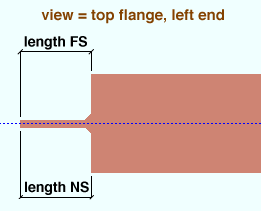
Top/Bottom flange length NS (
obj .TopLengthNSLeftorobj .TopLengthNSRightorobj .BottomLengthNSLeftorobj .BottomLengthNSRight): The distance from the (left or right) end of the material along the length of the near side of the top/bottom flange.Top/Bottom flange length FS (
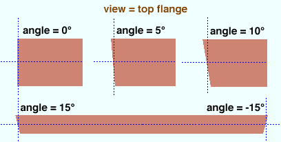
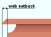
obj .TopLengthFSLeftorobj .TopLengthFSRightorobj .BottomLengthFSLeftorobj .BottomLengthFSRight): The distance from the (left or right) end of the material along the length of the far side of the top flange."Clip flange" : For wide flange or W tee " Section sizes ," this option designates a linear cut from the edge of the flange to the radius of the web at the angle designated by the " Flange cut angle ." If the " Flange cut angle " is 0 or the " Section size " is angle, pipe, tube or channel, a " Clip flange " does not take place.
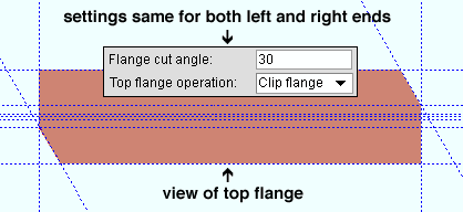
In this example, the " Flange cut angle " is positive . Notice that the clip on the left end is on the near side of the flange, while the clip on the right end is on the far side of the flange. "Notch" : Applies to HSS rectangular (tube) or HSS round (pipe) material only.
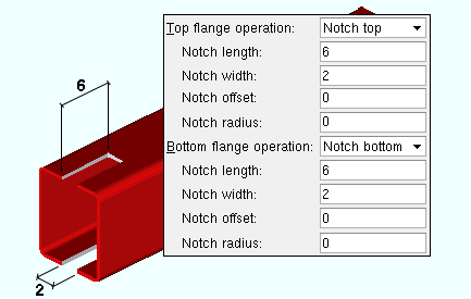
Notch length (
obj .TopLengthLeftorobj .TopLengthRightorobj .BottomLengthLeftorobj .BottomLengthRight)Notch width (
obj .TopWidthLeftorobj .TopWidthRightorobj .BottomWidthLeftorobj .BottomWidthRight)"Notch NS/FS" : Applies to HSS rectangular (tube) or HSS round (pipe) material only.
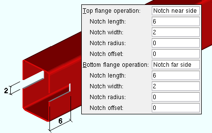
Notch length (
obj .TopLengthLeftorobj .TopLengthRightorobj .BottomLengthLeftorobj .BottomLengthRight)Notch width (
obj .TopWidthLeftorobj .TopWidthRightorobj .BottomWidthLeftorobj .BottomWidthRight)
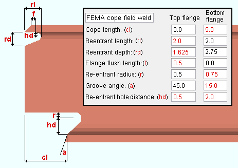
Cope length (
obj .TopLengthLeftorobj .TopLengthRightorobj .BottomLengthLeftorobj .BottomLengthRight)Re-entrant length (
obj .TopFEMAReEntrantLengthLeftorobj .TopFEMAReEntrantLengthRightorobj .BottomFEMAReEntrantLengthLeftorobj .BottomFEMAReEntrantLengthRight)Re-entrant depth (
obj .TopFEMAReEntrantDepthLeftorobj .TopFEMAReEntrantDepthRightorobj .BottomFEMAReEntrantDepthLeftorobj .BottomFEMAReEntrantDepthRight)Flange flush length (
obj .TopFEMAFlangeFlushLengthLeft or obj .TopFEMAFlangeFlushLengthRightorobj .BottomFEMAFlangeFlushLengthLeftorobj .BottomFEMAFlangeFlushLengthRight)Re-entrant radius (
obj .TopReEntrantRadiusLeftorobj .TopReEntrantRadiusRightorobj .BottomReEntrantRadiusLeftorobj .BottomReEntrantRadiusRight)Groove angle (
obj .TopGrooveAngleLeftorobj .TopGrooveAngleRightorobj .BottomGrooveAngleLeftorobj .BottomGrooveAngleRight)Re-entrant hole distance (
obj .TopReEntrantHoleDistanceLeftorobj .TopReEntrantHoleDistanceRightorobj .BottomReEntrantHoleDistanceLeftorobj .BottomReEntrantHoleDistanceRight)
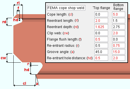
Cope length (
obj .TopLengthLeftorobj .TopLengthRightorobj .BottomLengthLeftorobj .BottomLengthRight)Re-entrant length (
obj .TopFEMAReEntrantLengthLeftorobj .TopFEMAReEntrantLengthRightorobj .BottomFEMAReEntrantLengthLeftorobj .BottomFEMAReEntrantLengthRight)Re-entrant depth (
obj .TopFEMAReEntrantDepthLeftorobj .TopFEMAReEntrantDepthRightorobj .BottomFEMAReEntrantDepthLeftorobj .BottomFEMAReEntrantDepthRight)Clip web (
obj .TopFEMAClipLeftorobj .TopFEMAClipRightorobj .BottomFEMAClipLeftorobj .BottomFEMAClipRight)Flange flush length (
obj .TopFEMAFlangeFlushLengthLeft or obj .TopFEMAFlangeFlushLengthRightorobj .BottomFEMAFlangeFlushLengthLeftorobj .BottomFEMAFlangeFlushLengthRight)Re-entrant radius (
obj .TopReEntrantRadiusLeftorobj .TopReEntrantRadiusRightorobj .BottomReEntrantRadiusLeftorobj .BottomReEntrantRadiusRight)Groove angle (
obj .TopGrooveAngleLeftorobj .TopGrooveAngleRightorobj .BottomGrooveAngleLeftorobj .BottomGrooveAngleRight)Re-entrant hole distance (
obj .TopReEntrantHoleDistanceLeftorobj .TopReEntrantHoleDistanceRightorobj .BottomReEntrantHoleDistanceLeftorobj .BottomReEntrantHoleDistanceRight)
" General Information " opens the Parametric General Information window so that you can assign a " Description " or " Material usage description " or " Material routing " to this material. Making entries to the Parametric General Information window adds extra lines to the script. Those extra lines override default settings.
"OK" (or the Enter key) closes this window and saves your changes to RAM.
"Cancel" (or the Esc key) closes this window without saving any changes that you have made to it.
"Reset" undoes all changes made to this window since you first opened it. The window remains open.

