 Tekla EPM Export (a.k.a. FabSuite Export )
Tool summary :
Also see :
- Kiss Export Setup (setup options for FabSuite Export )
- KissExport (alternative format)
- BIF (alternate export format for all users)
- Joists (not exported using FabSuite Export )
- Exporting from your current Job (index)
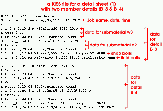
![]() Example of the KISS format :
Example of the KISS format :
|
' Model ' is this file's " Data source ." A detail sheet with two member details on it ( B_3 and B_4) was selected during export. If the " Data source " had been ' BOM ', you would not get the labor information (lines beginning with L ), which provide data on the number of holes, cuts etc. |
Step-by-step instructions :
The following step-by-step procedure tells you how to output a file in the KISS file format from your current Job . Additionally, it explains how to export copies of various types of Drawing Editor drawings and/or CNC files along with the KISS file.
1 . Before using this tool:
1a : Set up the Kiss Export Setup options in Fabricator Options so that drawings are exported in the correct " Drawing format " and the FabSuite KISS file includes the information you want.
1b : Confirm that your current Job includes the members and materials that you want to export information about.
1c : Confirm that the default output configuration entered for User and Site Options > Output > " Estimating/Production " is the one you want.
1d : The entire SDS2 3D model should have undergone Process and Create Solids before you export.
1e (optional) : If ' BOM ' is the " Data source " set in Kiss Export Setup , then Detail Member and Edit Bill operations should be done on the members you plan to select for inclusion in the FabSuite KISS file. Members must also be detailed in order to export copies of their drawings. To export member details, the box "
Details " needs to be checked in Kiss Export Setup . The member details will be output in the " Drawing format " (' PDF ' or ' DWG ' or ' DXF ' or ' DXB ' or ' DNG ') that is specified in Kiss Export Setup . Member details, if output, are placed in the
Fabrication folder.
1f (optional) : If you want to export data from selected detail sheets, details need to have been placed onto detail sheets . This applies regardless of the " Data source ." To actually export copies of the sheets themselves, the box for "
1g : (optional) : To export drawings of submaterial, submaterials need to have been Detailed and "
1h : To output CNC files to a
1i : To export drawings of erection sheets to an
2 . Start the FabSuite Export using any one (1) of the following methods.
▸ Home > Export > FabSuite(Tekla EPM) KISS
▸ If you are in Modeling or the Drawing Editor click the icon pictured above , or use a keyboard shortcut. The command group for Tekla EPM Export is Interface.
3 . The FabSuite Export window opens.
FabSuite folder: The name of the folder (up to 30 characters) that the FabSuite KISS file (and folders containing drawings or CNC files) will be placed into. The KISS file that this procedure generates will be named after the " FabSuite folder " and given a .kss extension. The default entry to this field is the name of your current Job .

Alternative 1 : Press the " OK " button to continue.
Alternative 2 : Press the " Cancel " button to end this operation and keep everything as it was before step 2.
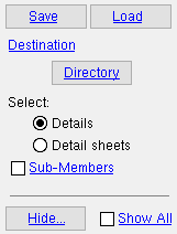
4 . A selection dialog opens with a list of details (or sheets ) that you can select for inclusion in the FabSuite file.
|
Optional for ' |
4a (optional) : Press the button under the " Destination " heading if you want the FabSuite file and file folders containing drawings to be output to a location other than that set per User and Site Options > Output > " Estimating/Production ."
4b : '
Details ' lists those details , including user created details , that are up to date and therefore not marked for detailing . '
4c : Select the names of the particular items (details or detail sheets) that you want to be included in the to-be-generated file, then press the " OK " button.
4d (if applicable) : If you are outputting CNC files and "
5 . The FabSuite KISS file is output to a file folder in the location set for the User and Site Options > Output > " Estimating/Production " output configuration (unless you changed this in step 4a). The name of that file folder is the " FabSuite folder ." The name of the FabSuite KISS file is the " FabSuite folder " plus a .kss extension. In addition to the FabSuite KISS file, you will find the following folders:
The
The
The
The

