 Cut Layout Command
- Step-By-Step
- Edit Depth
- Edit Shape
- Undo
- Tips and Tricks
- Related Tools
1 . Before using this tool:
1a : Go to a view that is perpendicular to the cut that you want to make. If you want the cut in a plane that is perpendicular to a particular surface, use one of the surface tools to snap to that surface. Set the depth check limits of the view to (or beyond) the limits of the cut you intend to make. Cut Layout cuts the material to the depth checking limits of the view and not any further.
1b : Place construction lines so that there are INCL points where you want to locate the lines that define the cut layout.
2 . Preselect a material to enable the Materials contextual page and click the Cut Layout icon found in the Operations section. Skip step 3.
Alternative : Invoke Cut Layout using the Find Tool by searching the command name and clicking the Cut Layout icon, which is pictured above. Proceed to step 3.
Learn more about alternative methods for launching commands.
3 . Skip this step if you already selected one or more materials in step 2.
3a : Cut Layout prompts you to use Select Item(s) mouse bindings to select one or more materials that you want to cut. This prompting also occurs, along with the clearing of all preselected items, when a member or other non-material item is preselected. Press the Enter key or right-click ( Menu ) and choose " OK " on the context menu to signal to Cut Layout that you are done selecting the material(s).
|
|
|
Select Item(s) mouse bindings |
4 . The status line prompts, "Locate point." "Locate- Pan -Return mouse bindings become active along with various Locate options. Corner rounding options also appear on the Corner Rounding section on the Layout page. After you locate the first point, the status line prompts, "Locate second point" and Locate - Complete - Return mouse bindings become active.
|
|
|
bindings |
|
|
|
bindings |
|
Corner rounding can be used to cut a circle in a plate. Without corner rounding, the same layout of points gets you a square. |
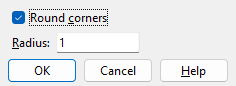
4a (optional) : If you want all of the corners of your cut layout to be rounded, check the box for " Round corners " and enter a " Radius ." If you want corners with different radiuses or some corners without rounding, remember that corner rounding applies to the point just located and must be applied before the next point is located.

bindings
4b : Select the appropriate Locate icon , place the mouse pointer (
) so that the point location target (
) snaps to a corner of your cut layout, then left-click ( Locate ).
4c : Repeat steps 4a and 4b to define other corners of the cut layout. Cut Layout draws lines between the points to indicate the outline of the cut layout.
4d : When you are done defining the cut layout, either left-click ( Locate ) the first point you located to close the cut outline, or middle-click ( Complete ) anywhere to draw a cut line between the last point located and the first point, thus closing the cut outline.
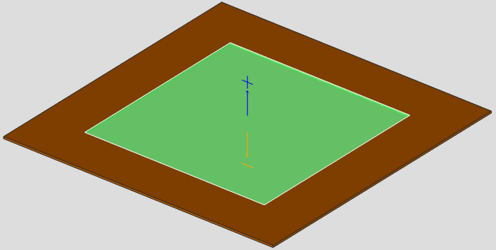
5 . The status line prompts, "Verify material cut. " Your computer screen redraws to show the cut . Yes - No mouse bindings become active.
|
|
|
bindings |
Alternative 1 : Left-click ( Yes ) to accept the cut as shown. Go to step 6.
Alternative 2 : Right-click ( No ) to cancel the Cut Layout operation and keep everything as it was before step 2. Do not continue.
6 . (if you selected one material in step 2 or 3) The Change All Options window opens. On it is a " Warnings " list. Material change " Options " become active along with the Warnings if the 3D model contains other pieces of material with the same submaterial piecemark as the one material you performed this operation on.

Alternative 1 : Make the appropriate selections on this window, then press the " OK " button at the bottom of the window to regenerate the material. The Cut Layout is now stored on the material as a Material Operation.
Alternative 2 : Press the " Cancel " button to end the Cut Layout operation and keep everything as it was before step 2.
1 . In the view in which you want to edit the Cut Layout operation, display in solid form all members that you want to edit.
Alternative 1 :View > Solid Opaque to display in solid form the members that you want to edit.
Alternative 2 :View > Change All to Solid to display in solid form all members that are in the view.
2 . In the view in which you want to perform the edit do one of the following:
▸ Run the Show Material Operations (if the cut operation is not shown). Double-click the cut or select the cut, right click, and select Edit.
▸ Using the Model Tree, expand the member and material subclasses, and select the cut layout operation. Doing it this way does not require the Material Operations to be shown.
▸ Edit the material that the cut is on, select material operations, and select edit next to the cut you wish to change.
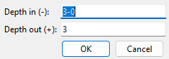
3 . A Depth In (-) and Depth Out (+) dialog opens. This dialog allows you to edit the depth of the cut, both in and out of the screen. The direction of the cuts are shown when the cut is edited, the axis will match what is in the dialog. To finish press the " OK " button.
4 . The Change All Options window opens. On it is a " Warnings " list and " Options ."
4a : Optionally select the " Options " you want, then press the " OK " button.
5 . The material is regenerated per the settings on the edit window.
▸ If trying to edit the geometry of a cut, there are three tools that can be used. These will likely be used in conjunction with each other. See Add Layout Node, Delete Layout Nodes, and Move Layout Nodes for more information.
▸ If you wish to set a node (layout point) to have the round corners checked or to set the radius do the following:
1 . In the view in which you want to remove the Cut Layout operation, display in solid form all members that you want to edit.
Alternative 1 :View > Solid Opaque to display in solid form the members that you want to edit.
Alternative 2 :View > Change All to Solid to display in solid form all members that are in the view.
2 . In the view in which you want to edit the Layout Node, the material operation must be shown using Show Material Operations.
3 . Edit the Layout Node either by double-clicking on the node or selecting the node, right-clicking, and selecting edit.
4 . Make the changes as you wish. To finish press the " OK " button.
Note: If a cut is added to multiple materials at the same time, the cuts are stored per material, and not as one single cut.
▸
1 . Open the cut material's edit window (e.g., double-click the material, or hover the material and right-click ( Menu ) and choose " Edit Other " on the context menu ).
1a : Press the " Material Operations " button at the bottom of the material edit window.
2 . A dialog opens showing each of the cut layout operations that appear on this material.
2a : Check the " Delete " check box next to the Cut Layout operation you wish to delete. If you want to delete multiple, you can select more than one. If you wish to remove all cut operations, select the " Delete All " check box.
2b : Press the " Close " button at the bottom of the material operations window.
2c : Press the " OK " button at the bottom of the material edit window.
3 . The Change All Options window opens. On it is a " Warnings " list and " Options ."
3a : Optionally select the " Options " you want, then press the " OK " button.
4 . The material is regenerated per the settings on its edit window. In other words, the cut layout with the delete check box checked disappears.
Note: If other pieces with the same submaterial piecemark exist in the 3D model and you selected the appropriate " Options ," then other materials are also regenerated as specified on the edit window.
▸
1 . In the view in which you want to remove the Cut Layout operation, display in solid form all members that you want to edit.
Alternative 1 :View > Solid Opaque to display in solid form the members that you want to edit.
Alternative 2 :View > Change All to Solid to display in solid form all members that are in the view.
2 . Select the cut layout operation by doing the following:
Alternative 1 : Run the Show Material Operations tool if they are not shown. Once the material operation is shown, select the Cut Layout.
Alternative 2 : Using the Model Tree, expand the member and material subclasses, and select the cut layout operation.
3 . Once the cut layout operation is selected, do the following to delete the operation:
Alternative 1 : Select The Delete key on the keyboard.
Alternative 2 : Select the Delete
icon.
- Depth checking (affects depth of cut)
- Cut on Plane (also for cutting material)
- Flat Plate Layout (alternative for plate)
- Material Operations

