 Export Model - EM11(IFC2x3)
- General Overview
- Step-By-Step
- Tips and Tricks
- Related Tools
Export zipped file: ![]() or
or ![]() . If this box
. If this box ![]() is checked, the file will be exported as a zipped file (.ifcZIP).
If this box
is checked, the file will be exported as a zipped file (.ifcZIP).
If this box ![]() is not checked, the file will be exported as an uncompressed EM11 IFC file (.ifc).
is not checked, the file will be exported as an uncompressed EM11 IFC file (.ifc).
Export custom properties: ![]() or
or ![]() . If this box
. If this box ![]() is checked, the IFC file will include custom properties, which can be used by other programs that are capable of interpreting meta data. Only those custom properties that have
is checked, the IFC file will include custom properties, which can be used by other programs that are capable of interpreting meta data. Only those custom properties that have ![]() Export to IFC turned on in their schema entry will be included in the IFC export file. Depending on whether the custom property is for members or material or etc., each member or material will have its unique custom property assignment accurately recorded. If the box
Export to IFC turned on in their schema entry will be included in the IFC export file. Depending on whether the custom property is for members or material or etc., each member or material will have its unique custom property assignment accurately recorded. If the box ![]() is not checked, custom property information will not be included in the IFC file.
is not checked, custom property information will not be included in the IFC file.
Export only main materials: ![]() or
or ![]() . If this box
. If this box ![]() is checked, only the main member materials are output to the IFC file. If this box
is checked, only the main member materials are output to the IFC file. If this box ![]() is not checked, all materials are output to the export file.
is not checked, all materials are output to the export file.
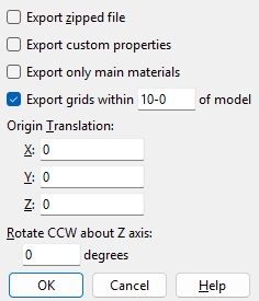
Export grids within distance of model:
![]() or
or ![]() . If this box
. If this box ![]() is checked, then grid lines in SDS2 within the specified distance are converted into a form of lines that can be read by other programs. They are exported at the bottom of the lowest material being exported. If the box
is checked, then grid lines in SDS2 within the specified distance are converted into a form of lines that can be read by other programs. They are exported at the bottom of the lowest material being exported. If the box ![]() is not checked, grids will not be included in the IFC file.
is not checked, grids will not be included in the IFC file.
Output material color:Model color or Surface finish. When Model color is selected materials will be output in the color shown in the model. Generally, this will be the Color that is selected on their material edit windows or, if you are exporting while in Modeling, their status display colors. Select Surface finish to output materials in a color that matches the Surface finish that is selected for those materials on their material edit windows.
Origin translation: 0 or a +/- distance. Use this setting to shift the coordinates of every member by a specific distance in X, Y, and/or Z in the exported file.
A positive distance is added to the X, Y and/or Z coordinates of all exported members.
A negative distance is subtracted from the X, Y and/or Z coordinates of all exported members.
Rotate CCW (counterclockwise) around Z axis: A positive or negative (-) number of degrees. Rotation is around the Z global axis .
A value of 0 designates no rotation of the EM11 IFC model, with the result that members will be oriented as they are in the SDS2 3D model.
A positive number rotates the EM11 IFC model counterclockwise that number of degrees.
A negative number rotates the EM11 IFC model clockwise that number of degrees.
OK (or the Enter key) closes this screen and applies the settings.
Cancel (or the Esc key) closes this screen without saving any changes.
1 . Click the Export Model icon, which is pictured above. The icon can be found on the Import/Export page > Model section.
Method 2: Click Export Model on the home screen. The command can be found on the Export tab in the 3D section. Skip step 2.
Alternative: Use the Find Tool by searching the command name and clicking the Export Model icon, which is pictured above.
Learn more about alternative methods for launching commands.
2 . The status line prompts Select members, and the Select - Pan - Menu mouse bindings become active. Select the member(s), then press Enter or right-click and select OK.
Alternative: Press the Esc key or right-click and select Cancel to end the command.
3 . The Export Model window opens. Select EM11 (IFC2x3) as the Export file format. Set the Destination where you want the file to be sent. Directory outputs the file to a folder. Select Properties to open the EM11 Properties window (as shown on the General Overview tab).
4 . Select OK to export the .ifc file.
Alternative: Press the Esc key or select Cancel to end the command.

