 Add Beam Flange to Flange Connection ( Modeling )
Tool summary :
-
Field bolts the flanges of two wide flange beams that cross one another at different elevations. A filler plate is provided if one is needed.
-
The two beams can be rolled (weak axis) and do not have to be perpendicular to one another. The field bolts are placed along the flange gage of the upper beam.
A [ Beam Flange to Flange Connection ] section containing the same options that are shown here can be found on the edit window of the beam that you selected before adding the component. The bill of material and detail of that member will also show the fill plate (if one is needed). Flange holes added with this component are detailed on both of the crossing beams.
Also see :
- Modeling (where custom components can be added)
- Custom components (topic)
- Component Plugin Setup ( Home > Project Settings > Job > Plugin Defaults >)
- Explode Component (makes the component no longer a component)
- Component Selection Tool (to search for custom components of a selected type)
- Model Tree (to find custom components and select them for deletion, editing, etc.)
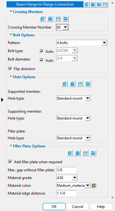
To add, edit, or delete a Beam Flange to Flange Connection :
Beam Flange to Flange custom component settings :
| ------- |
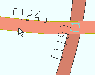
Crossing member number: -1 or a member number . This list box lists the member number of each of the beams that cross the beam that was selected to add this component. You must select a member number to get a connection.
|
Member [124] in this example is the beam that was selected when the Beam Flange to Flange Connection component was added. Member [119] is the " Crossing member ." Weak axis rolling operations have been applied to both beams. |
' -1 ' is the only choice on this list box if the beam that was selected when the Beam Flange to Flange Connection component was added does not have another beam that crosses immediately above it or immediately below it. ' -1 ' is applied automatically in the event that you have deleted a crossing beam that was originally connected by this Beam Flange to Flange Connection component.
' a member number ' designates that Beam Flange to Flange Connection connect to the one beam that has been assigned that selected member number . No two members in the model are ever assigned the same member number.
| ------- |
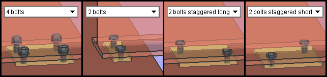
Pattern: 4 bolts or 2 bolts or 2 bolts staggered long or 2 bolts staggered short .
|
|
Filler plates are shown in these examples. A connection gets a filler plate when " |
' 4 bolts ' is an option when the top beam's bottom flange sits on or slightly above the full flange of the lower beam.
' 2 bolts ' is the only choice when the top beam's bottom flange bears on half the flange of the lower beam.
' 2 bolts staggered long ' is an option when the top beam's bottom flange sits on or slightly above the full flange of the lower beam. It staggers the bolts at an angle perpendicular to the angle at which ' 2 bolts staggered short ' staggers the bolts.
' 2 bolts staggered short ' is an option when the top beam's bottom flange sits on or slightly above the full flange of the lower beam. It staggers the bolts at an angle perpendicular to the angle at which ' 2 bolts staggered long ' staggers the bolts.
Bolt type: ![]() Auto or
Auto or ![]() Auto . This sets the type of field bolt to be used for connecting the flanges of the beams..
Auto . This sets the type of field bolt to be used for connecting the flanges of the beams..
'
Auto (checked) ' instructs Beam Flange to Flange Connection to use the " Bolt type " for " Non-moment bolts " that is set at Home > Project Settings > Job > Bolt Settings .
'
Auto (not checked) ' permits you to choose a bolt type from the list box (
). The choices found on the list box's menu come from Home > Project Settings > Job > Bolt Specifications .
Bolt diameter: ![]() Auto or
Auto or ![]() Auto . This sets the diameter (inches or mm) of the shanks of the field bolts to be used for connecting the flanges of the beams.
Auto . This sets the diameter (inches or mm) of the shanks of the field bolts to be used for connecting the flanges of the beams.
| diameter |
|
'
'
If this box is checked (
If the box is not checked (
------- Hole Options ------
Supported member hole type: Standard round or Short slot or Oversized round or Long slot . The supported member is the upper beam. This sets the hole type through the bottom flange of the upper beam. Hole type definitions can be found in Table J3.3 or Table J3.3M ( AISC Thirteenth Edition , p. 16.1-105).

' Standard round ' designates a round hole.
' Short slot ' designates an oblong hole with a relatively short slot length and a diameter that is typically 1/16 inch larger than the input bolt diameter. Selecting ' Short slot ' results in options appearing for " Slot length " and " Slot rotation ."
' Oversize ' designates an oversized round hole.
' Long slot ' designates an oblong hole with a relatively long slot length and a diameter that is typically 1/16 inch larger than the input bolt diameter. Selecting ' Long slot ' results in your also getting options for " Slot length " and " Slot rotation ."
Supporting member hole type: Standard round or Short slot or Oversized round or Long slot . The supporting member is the lower beam. This sets the hole type through the top flange of the lower beam. Hole type definitions can be found in Table J3.3 or Table J3.3M ( AISC Thirteenth Edition , p. 16.1-105).
' Standard round ' designates a round hole.
' Short slot ' designates an oblong hole with a relatively short slot length and a diameter that is typically 1/16 inch larger than the input bolt diameter. Selecting ' Short slot ' results in options appearing for " Slot length " and " Slot rotation ."
' Oversize ' designates an oversized round hole.
' Long slot ' designates an oblong hole with a relatively long slot length and a diameter that is typically 1/16 inch larger than the input bolt diameter. Selecting ' Long slot ' results in your also getting options for " Slot length " and " Slot rotation ."
Filler plate hole type: Standard round or Short slot or Oversized round or Long slot . This sets the hole type through filler plate (if there is one). A filler plate is created when " ![]() Add filler plate when required " is checked and the gap between the beams is greater than the " Max gap without filler plate ," Hole type definitions can be found in Table J3.3 or Table J3.3M ( AISC Thirteenth Edition , p. 16.1-105).
Add filler plate when required " is checked and the gap between the beams is greater than the " Max gap without filler plate ," Hole type definitions can be found in Table J3.3 or Table J3.3M ( AISC Thirteenth Edition , p. 16.1-105).
' Standard round ' designates a round hole.
' Short slot ' designates an oblong hole with a relatively short slot length and a diameter that is typically 1/16 inch larger than the input bolt diameter. Selecting ' Short slot ' results in options appearing for " Slot length " and " Slot rotation ."
' Oversize ' designates an oversized round hole.
' Long slot ' designates an oblong hole with a relatively long slot length and a diameter that is typically 1/16 inch larger than the input bolt diameter. Selecting ' Long slot ' results in your also getting options for " Slot length " and " Slot rotation ."
-------
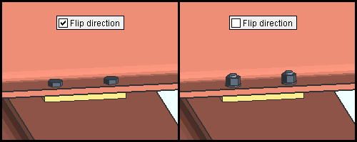
Add filler plate when required: ![]() or
or ![]() .
.
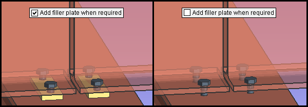
|
| The top beams in these examples are displayed in the form solid transparent main . The bottom beams are displayed in solid opaque form. |
If this box is checked (
If the box is not checked (
Max gap without filler plate: A distance (in the primary dimension " Units " or other units ).
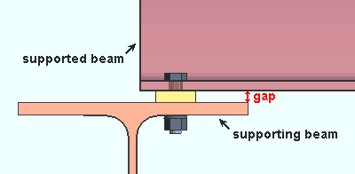
When the distance between the bottom flange of the supported beam and the top flange of the supporting beam exceeds the gap that is entered here, Beam Flange to Flange Connection will create a filler plate if the box for "
In other words, Beam Flange to Flange Connection determines whether or not a filler plate is required based on the entry that is made here.
Material grade: A36 or A572 or etc. The " Steel grade " of the rectangular plate material that the filler plate is made of.
Setup: If the grade of steel you want is not shown on the list box (
Material color: A predefined color or a custom color . The " Color " of the rectangular plate material that a filler plate is made of. This is the approximate color of the filler plate when the beam they are submaterials of is displayed in one of the three solid forms .
The predefined colors are set up on the Predefined Colors window. The color swatch next to the list box (
Select ' Custom Color ' (last choice on the list) to launch your operating system's color picker and define any color you like.
Material edge distance: The distance (in the primary dimension " Units " or other units ) from the center of any hole to the nearest edges of the filling plate. Each hole is placed this distance from a horizontal edge and this same distance from a vertical edge. In other words, the " Material edge distance " sets both the horizontal edge distance and the vertical edge distance for each hole in the plate.

|
| The " Pattern " in the above examples is set to ' 4 bolts ' (left) or ' 2 bolts ' (left, middle) or ' 2 bolts staggered long ' (middle, right) or ' 2 bolts staggered short ' (right). |

