"  End preparations " (for member main material)
On this page :
- General information about end preparations
- Member main material:
Also see :
- Rolled Section Material (another place with " End preparations " options)
- Weld Design Settings (setup for weld preparations #1 and #3)
- Seismic Weld Access Holes (setup for seismic weld preparation)
General information about end preparations :
Q. Where are end preparations found?
A . An "
End preparations " leaf can be found under " Left end settings " and " Right end settings " on the Beam Edit , Column Edit , Vertical Brace Edit , Horizontal Brace Edit , Girt (Legacy) Edit and Purlin Edit windows. The options also appear on the Connection Component Edit window.
Q. What do end preparations do?
A . End preparations control the end preparation on the left and right ends of a member's main material. Connection design uses the choices that you apply.
Q. Why use the member window instead of the material window?
A . Although the " Left/right end settings " on the Rolled Section Material window appear to be the same as the "
End preparations " on member edit windows, there is a difference. Changing the " Left/right end settings " causes the " Main material " to be set to '
'. However, if you change a member's end preparations, the " Main material " will continue to be set to '
'. When the " Main material " is set to ' SYSTEM ', the Connection Calculations and Expanded Calculations will more accurately reflect the state of the model.
Q . Are end preparations saved with user defined connections?
A . Yes. If you save a user defined connection from the Beam Edit , Column Edit , Horizontal Brace Edit , Vertical Brace Edit , Joist Edit or the Connection Component Edit window, the "
End preparations " from that window are included in the user defined connection.
---- Member main material ----
End-cut type: Standard cut or Square cut or Bevel cut or Mill cut . To make an entry, you need to lock ( ![]() ) this field. If this field is unlocked (
) this field. If this field is unlocked ( ![]() ), the appropriate cut is automatically selected for you.
), the appropriate cut is automatically selected for you.
|
The left/right " End-cut type " on the member's main material will match the " End-cut type " entered here. During Detail Members , an annotation will be added to the detail if the " End-cut type " is a choice other than ' Standard cut '. |
Tip: By changing the " End-cut type " here, on the member, instead of changing the " End-cut type " on the member's main material, the " Main material " stays set to '
'. Changing the " End-cut type " on the material resets the " Main material " to '
'.
' Standard cut ' instructs Detail Members to not annotate the member detail with special cut instructions. The designation ' None ' is entered to the " End Prep " column on an ABM Report for member main materials with a ' Standard cut ' selected on both ends.
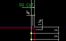
' Square cut ' instructs Detail Members to apply the annotation " SQ CU T" (as illustrated above) to the appropriate end of the member detail. The instruction ' S1E ' is entered to the " End Prep " column on an ABM Report .
' Bevel cut ' instructs Detail Members to apply the annotation " BEV CUT " to the appropriate end on the member detail. The instruction " B2E " is entered to the " End Prep " column on an ABM Report for member main materials with a ' Bevel cut ' on both ends. The program automatically selects ' Bevel cut ' on main material for sloping beam-to-beam connections or sloping beam-to-column connections, column-to-sloping beam connections, and beam-to-rotated beam connections. ' Bevel cut ' is automatically selected when a value other than zero is entered as the " Web cut angle ."
' Mill cut ' instructs Detail Members to apply the annotation " MILL CUT " to the appropriate end on the member detail. The instruction " M2E " is entered to the " End Prep " column on an ABM Report for member main materials whose both ends are ' Mill cut '. When the option " Mill cut ends of columns " is checked, ' Mill cut ' is automatically applied to the ends of columns framing squarely to other members or to base plates.
Report Writer: Member.LeftEnd.MoreEnd.EndPreparationDescription
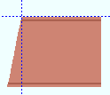
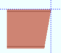
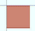
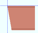
Web cut angle: A positive or negative angle from 89 to -89 degrees. Angles closer to zero than .057 degrees are rounded to zero when the member main material is regenerated (after you press " OK "). ' 0 ' specifies that no web cut be made. To make an entry, you need to lock ( ![]() ) this field. If this field is unlocked (
) this field. If this field is unlocked ( ![]() ), connection design automatically calculates the appropriate web cut angle based on the actual framing situation in the model.
), connection design automatically calculates the appropriate web cut angle based on the actual framing situation in the model.
| left | right | left & right | left | right |
-10 degrees
 |
-10 degrees
 |
0 degrees
 |
10 degrees
 |
10 degrees
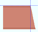 |
Assuming that you are viewing the near side of the member main material, a positive angle is measured counterclockwise from a perpendicular bisector to the workline. A negative (-) angle is measured clockwise from a perpendicular bisector to the workline.
Note: Length may be added to the member main material as a result of this operation.
Report Writer: Member.LeftEnd.MoreEnd.AngleOfEndWebCut
Advanced Selection: m.Ends[0].AngleOfEndWebCut
Parametric module: m.Ends[0].AngleOfEndWebCut
Flange cut angle: A positive or negative angle from 89 to -89 degrees. This is the angle at which both the near and far side of the flange are to be cut. ' 0 ' designates that no flange cut be made. To make an entry, you need to lock ( ![]() ) this field. If this field is unlocked (
) this field. If this field is unlocked ( ![]() ), connection design automatically calculates the appropriate flange cut angle based on the actual framing situation in the model. Also see: ' Clip flange '.
), connection design automatically calculates the appropriate flange cut angle based on the actual framing situation in the model. Also see: ' Clip flange '.
| wide flange | ||||
| left | right | left & right | left | right |
-10 degrees
 |
-10 degrees
 |
0 degrees
 |
10 degrees
 |
10 degrees
 |
| angle (or channel) | ||||
| left | right | left & right | left | right |
-10 degrees
 |
-10 degrees
 |
0 degrees
 |
10 degrees
 |
10 degrees
 |
Assuming that the left end of the flange (horizontal leg of an angle) is to your left in your current view, a ' positive angle ' is measured counterclockwise from a perpendicular bisector to the flange center line (to the back of an angle or channel). A ' negative (-) angle ' is measured clockwise from a perpendicular bisector to the flange center line (to the back of an angle or channel).
Note: Length may be added to the member main material as a result of this operation.
Report Writer: Member.LeftEnd.MoreEnd.AngleOfEndFlangeCut
Advanced Selection: m.Ends[0].AngleOfEndFlangeCut
Parametric module: m.Ends[0].AngleOfEndFlangeCut
Moment connection web setback: The distance (in the primary dimension " Units " or other units ) that you want the web of this member main material to be set back. To make an entry, you need to lock ( ![]() ) this field. If this field is unlocked (
) this field. If this field is unlocked ( ![]() ), connection design automatically applies the appropriate web setback based on setup choices.
), connection design automatically applies the appropriate web setback based on setup choices.

|
s = moment connection web setback. |
End connection failure messages: The " Moment connection web setback " applies when ' Cope shop weld #3 (Standard) ' or ' Cope field weld #3 (Standard) ' or ' Cope field weld #1 (FEMA) ' or ' Cope shop weld #1 (FEMA) ' or ' Seismic cope field weld ' or ' Seismic cope shop weld ' is the " Top operation " or the " Bottom operation ." For any other " Top/bottom flange operation ," a non-zero entry to this field gives you the connection failure message. " Cannot have a moment web setback without a cope weld end operation ." Also, if you have applied cope operations to both the top and bottom flanges, you get the failure message " Cannot have a moment web setback with both flanges coped ."
Setup: A web setback applied here may be used to override the choice made to " Web setback dimension for moment connections " in Weld Design Settings . For a seismic connection, it overrides the " Web setback " in Seismic Weld Access Holes .
Top/Bottom flange operation: None or Cope plain or Cope shop weld #3 (Standard) or Cope field weld #3 (Standard) or Cut flange flush or Clip flange or Notch top/bottom or Notch near side/far side or Cope field weld #1 (FEMA) or Cope shop weld #1 (FEMA) or Clip web or Seismic cope field weld or Seismic cope shop weld . Also click here . To make an entry, you need to lock ( ![]() ) this field. If this field is unlocked (
) this field. If this field is unlocked ( ![]() ), connection design automatically applies ' None ' as the flange operation. /P>
), connection design automatically applies ' None ' as the flange operation. /P>
CNC downloading: The DSTV " CNC configuration type " can download any weld preparation set here.
Advanced Selection: m.Ends[0].TopOperationType or m.Ends[0].BottomOperationType
Parametric module: m.Ends[0].TopOperationType or m.Ends[0].BottomOperationType' None ' designates that no top/bottom flange cutting operation be performed on this member's main material.
' Cope plain ' or ' Cope shop weld #3 (Standard) ' or ' Cope field weld #3 (Standard) ' generate weld preparation and / or a cut to remove part of the top/bottom flange plus part of the web. ' Cope shop weld #3 (Standard) ' or ' Cope field weld #3 (Standard) ' work best for wide flange or S Shape or W tee or S tee main material; ' Cope plain ' works for all material types. Tip: A " Cope length " of ' 0 ' for ' Cope shop weld #3 (Standard) ' or ' Cope field weld #3 (Standard) ' causes weld preparation without a coping operation. CNC: " Add holes " in CNC Setup can be set to ' In copes ' or ' In all radii ' to download the cope hole (or weld prep hole). Setup: Weld Design Settings , " Cope cut type " (for ' Cope plain '),."
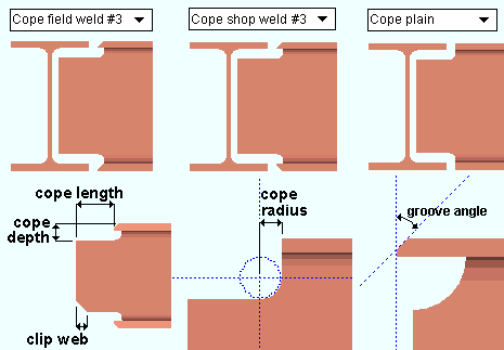
" Cope length " is the distance parallel with the main material's longitudinal axis ( X material axis ) from the (left or right) end of the member to the flange. Entries must either be ' 0 ' or greater than or equal to '1/2' inch ('13' mm).
" Cope depth " is the distance from the top of the top flange (or bottom of the bottom flange) into the web of the material. The cope depth is measured parallel with the " Web cut " angle, or -- for ' Cope plain ', if the " Cope cut type " is ' Parallel to flange ' -- it is measured perpendicular to the flange.
" Cope radius Setup: that is less than this minimum, your entry will be changed to the minimum." Cope depth " If you try to enter a ". Cope radius " must be, at least, the flange thickness plus the " Cope depth " operation. The " Cope plain " sets the curvature at the corner for a " Home > Project Settings > Fabricator > Member Detailing/Fabricator Options > the " Beams " section > " Cope radius ."
" Clip web " is an option when ' Cope shop weld #3 (Standard) ' is the selected " Top/bottom flange operation ."
" Groove angle " sets the angle of the flange bevel to anywhere within the allowable limit of +/- 75 degrees.
Advanced Selection: m.Ends[0].TopDimension1 or m.Ends[0].BottomDimension1
Advanced Selection: m.Ends[0].TopDimension2 or m.Ends[0].BottomDimension2
Advanced Selection: m.Ends[0].TopDimension3 or m.Ends[0].BottomDimension3
Advanced Selection: m.Ends[0].TopDimension6 or m.Ends[0].BottomDimension6
Advanced Selection: m.Ends[0].TopDimension7 or m.Ends[0].BottomDimension7Parametric module: m.Ends[0].TopDimension1 or m.Ends[0].BottomDimension1
Parametric module: m.Ends[0].TopDimension2 or m.Ends[0].BottomDimension2
Parametric module: m.Ends[0].TopDimension3 or m.Ends[0].BottomDimension3
Parametric module: m.Ends[0].TopDimension6 or m.Ends[0].BottomDimension6
Parametric module: m.Ends[0].TopDimension7 or m.Ends[0].BottomDimension7' Cut flange width ' works differently on different material types. When a wide flange or S Shape or W tee or S tee " Section size " has been entered as the main material for this member, this " Top/Bottom flange operation " setting designates two flange cuts, one on the near side and the other on the far side of the flange. For channel or angle member main material, it designates a single cut (on the flange or on one leg of the angle).
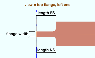
The ' Top/Bottom flange length NS ' is the distance from the (left or right) end of the member main material along the length of the near side of the top/bottom flange.
The ' Top/Bottom flange length FS ' is the distance from the (left or right) end of the member main material along the length of the far side of the top flange.
The ' Top/Bottom flange width ' is the flange width that remains after the NS and FS flange cuts are made.
Advanced Selection: m.Ends[0].TopDimension1 or m.Ends[0].BottomDimension1
Advanced Selection: m.Ends[0].TopDimension2 or m.Ends[0].BottomDimension2
Advanced Selection: m.Ends[0].TopDimension3 or m.Ends[0].BottomDimension3Parametric module: m.Ends[0].TopDimension1 or m.Ends[0].BottomDimension1
Parametric module: m.Ends[0].TopDimension2 or m.Ends[0].BottomDimension2
Parametric module: m.Ends[0].TopDimension3 or m.Ends[0].BottomDimension3' Cut flange flush ' works differently on different material types. When a wide flange or S Shape or W tee or S tee " Section size " has been entered for this member, this " Top/Bottom flange operation " setting designates two flange cuts, one on the near side and the other on the far side of the flange, both cuts to the web. Entering ' 0 ' to the ' Length NS ' or ' Length FS ' field stops a cut from being made at that location. For channel or angle member main material, it designates a single cut (on the flange or on one leg of the angle), and you need only enter " Flange length NS " if the material is toe in, " Flange length FS " if the material is toe out.
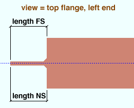
' Top/Bottom flange length NS ' is the distance from the (left or right) end of the material along the material's longitudinal axis ( X material axis ).
' Top/Bottom flange length FS ' is the distance from the (left or right) end of the material along the material's longitudinal axis ( X material axis ).
Advanced Selection: m.Ends[0].TopDimension1 or m.Ends[0].BottomDimension1
Advanced Selection: m.Ends[0].TopDimension2 or m.Ends[0].BottomDimension2Parametric module: m.Ends[0].TopDimension1 or m.Ends[0].BottomDimension1
Parametric module: m.Ends[0].TopDimension2 or m.Ends[0].BottomDimension2' Clip flange ' applies when the " Section size " is a wide flange or S Shape or W tee or S tee . It designates a linear cut from the edge of the flange to the radius of the web at the " Flange cut " angle. If the " Flange cut " is ' 0 ' or the " Section size " is angle, pipe, tube or channel, a ' Clip flange ' does not take place.
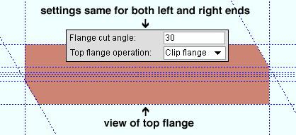
In this example, the " Flange cut " is positive. The left end clip is on the near side of the flange, while the clip on the right end is on the far side of the flange. ' Notch top ' or ' Notch bottom ' gives you distance entry fields for " Notch length " and " Notch width " and " Notch radius " and " Notch offset " that let you define the dimensions for a cut from the left/right edge of the HSS rectangular (or tube) or HSS round (or pipe) material into the center of the member main material's top or bottom wall.
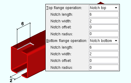
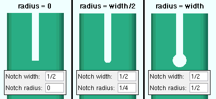
|
A " Notch radius " that is 1/2 the " Notch width " results in a half circle at the end of the slot. |
Setup: HSS notch radius (vertical braces), HSS notch radius (columns)
Setup: Total notch width clearance (vertical braces), Total notch width clearance (columns)Advanced Selection: m.Ends[0].TopDimension1 or m.Ends[0].BottomDimension1
Advanced Selection: m.Ends[0].TopDimension2 or m.Ends[0].BottomDimension2
Advanced Selection: m.Ends[0].TopDimension3 or m.Ends[0].BottomDimension3
Advanced Selection: m.Ends[0].TopDimension4 or m.Ends[0].BottomDimension4Parametric module: m.Ends[0].TopDimension1 or m.Ends[0].BottomDimension1
Parametric module: m.Ends[0].TopDimension2 or m.Ends[0].BottomDimension2
Parametric module: m.Ends[0].TopDimension3 or m.Ends[0].BottomDimension3
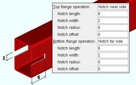
Parametric module: m.Ends[0].TopDimension4 or m.Ends[0].BottomDimension4' Notch near side ' or ' Notch far side ' gives you distance entry fields for " Notch length " and " Notch width " and " Notch radius " and " Notch offset " that let you define the dimensions for a cut from the left/right edge of the HSS rectangular or HSS round material into the center of the member main material's near side or far side wall.
Advanced Selection: m.Ends[0].TopDimension1 or m.Ends[0].BottomDimension1
Advanced Selection: m.Ends[0].TopDimension2 or m.Ends[0].BottomDimension2
Advanced Selection: m.Ends[0].TopDimension3 or m.Ends[0].BottomDimension3
Advanced Selection: m.Ends[0].TopDimension4 or m.Ends[0].BottomDimension4Parametric module: m.Ends[0].TopDimension1 or m.Ends[0].BottomDimension1
Parametric module: m.Ends[0].TopDimension2 or m.Ends[0].BottomDimension2
Parametric module: m.Ends[0].TopDimension3 or m.Ends[0].BottomDimension3
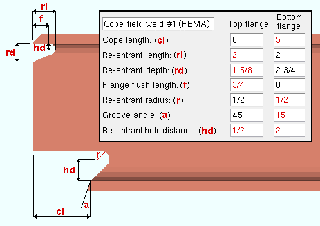
Parametric module: m.Ends[0].TopDimension4 or m.Ends[0].BottomDimension4' Cope field weld #1 (FEMA) ' gives you distance entry fields for " Cope length ," " Re-entrant length ," " Re-entrant cut depth " " Flange flush length " " Re-entrant radius " " Groove angle ." Setup: " Alternate 1 re-entrant cut radius " " Groove angle " " Alternate 1 re-entrant cut length " " Alternate 1 re-entrant cut depth " " Alternate 1 flange flush length ." CNC : " Add holes " in CNC Setup can be set to ' In copes ' or ' In all radii ' to download the weld prep hole.
Advanced Selection: m.Ends[0].TopDimension1 or m.Ends[0].BottomDimension1
Advanced Selection: m.Ends[0].TopDimension2 or m.Ends[0].BottomDimension2
Advanced Selection: m.Ends[0].TopDimension3 or m.Ends[0].BottomDimension3
Advanced Selection: m.Ends[0].TopDimension5 or m.Ends[0].BottomDimension5
Advanced Selection: m.Ends[0].TopDimension6 or m.Ends[0].BottomDimension6
Advanced Selection: m.Ends[0].TopDimension7 or m.Ends[0].BottomDimension7
Advanced Selection: m.Ends[0].TopDimension8 or m.Ends[0].BottomDimension8Parametric module: m.Ends[0].TopDimension1 or m.Ends[0].BottomDimension1
Parametric module: m.Ends[0].TopDimension2 or m.Ends[0].BottomDimension2
Parametric module: m.Ends[0].TopDimension3 or m.Ends[0].BottomDimension3
Parametric module: m.Ends[0].TopDimension5 or m.Ends[0].BottomDimension5
Parametric module: m.Ends[0].TopDimension6 or m.Ends[0].BottomDimension6
Parametric module: m.Ends[0].TopDimension7 or m.Ends[0].BottomDimension7
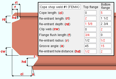
Parametric module: m.Ends[0].TopDimension8 or m.Ends[0].BottomDimension8' Cope shop weld #1 (FEMA) ' gives you distance entry fields for " Cope length ," " Re-entrant length ," " Re-entrant depth " " Clip web " " Flange flush length " " Re-entrant radius " " Groove angle " " Re-entrant hole distance ." Setup: " Alternate 1 re-entrant cut radius " " Groove angle " " Alternate 1 re-entrant cut length " " Alternate 1 re-entrant cut depth " " Alternate 1 flange flush length ." CNC : " Add holes " in CNC Setup can be set to ' In copes ' or ' In all radii ' to download the weld prep hole.
Advanced Selection: m.Ends[0].TopDimension1 or m.Ends[0].BottomDimension1
Advanced Selection: m.Ends[0].TopDimension2 or m.Ends[0].BottomDimension2
Advanced Selection: m.Ends[0].TopDimension3 or m.Ends[0].BottomDimension3
Advanced Selection: m.Ends[0].TopDimension4 or m.Ends[0].BottomDimension4
Advanced Selection: m.Ends[0].TopDimension5 or m.Ends[0].BottomDimension5
Advanced Selection: m.Ends[0].TopDimension6 or m.Ends[0].BottomDimension6
Advanced Selection: m.Ends[0].TopDimension7 or m.Ends[0].BottomDimension7
Advanced Selection: m.Ends[0].TopDimension8 or m.Ends[0].BottomDimension8Parametric module: m.Ends[0].TopDimension1 or m.Ends[0].BottomDimension1
Parametric module: m.Ends[0].TopDimension2 or m.Ends[0].BottomDimension2
Parametric module: m.Ends[0].TopDimension3 or m.Ends[0].BottomDimension3
Parametric module: m.Ends[0].TopDimension4 or m.Ends[0].BottomDimension4
Parametric module: m.Ends[0].TopDimension5 or m.Ends[0].BottomDimension5
Parametric module: m.Ends[0].TopDimension6 or m.Ends[0].BottomDimension6
Parametric module: m.Ends[0].TopDimension7 or m.Ends[0].BottomDimension7
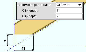
Parametric module: m.Ends[0].TopDimension8 or m.Ends[0].BottomDimension8' Clip web ' gives you distance entry fields for " Clip length " and " Clip depth ."
Advanced Selection: m.Ends[0].TopDimension1 or m.Ends[0].BottomDimension1
Advanced Selection: m.Ends[0].TopDimension2 or m.Ends[0].BottomDimension2Parametric module: m.Ends[0].TopDimension1 or m.Ends[0].BottomDimension1
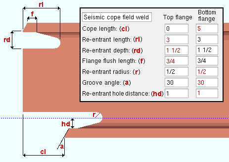
Parametric module: m.Ends[0].TopDimension2 or m.Ends[0].BottomDimension2' Seismic cope field weld ' gives you distance entry fields for " Cope length ," " Re-entrant length ," " Re-entrant depth " " Clip web " " Flange flush length " " Re-entrant radius " " Groove angle " and " Re-entrant hole distance ." Setup: Seismic Weld Access Holes . CNC : " Add holes " in CNC Setup can be set to ' In copes ' or ' In all radii ' to download the weld prep hole.
Advanced Selection: m.Ends[0].TopDimension1 or m.Ends[0].BottomDimension1
Advanced Selection: m.Ends[0].TopDimension2 or m.Ends[0].BottomDimension2
Advanced Selection: m.Ends[0].TopDimension3 or m.Ends[0].BottomDimension3
Advanced Selection: m.Ends[0].TopDimension5 or m.Ends[0].BottomDimension5
Advanced Selection: m.Ends[0].TopDimension6 or m.Ends[0].BottomDimension6
Advanced Selection: m.Ends[0].TopDimension7 or m.Ends[0].BottomDimension7
Advanced Selection: m.Ends[0].TopDimension8 or m.Ends[0].BottomDimension8Parametric module: m.Ends[0].TopDimension1 or m.Ends[0].BottomDimension1
Parametric module: m.Ends[0].TopDimension2 or m.Ends[0].BottomDimension2
Parametric module: m.Ends[0].TopDimension3 or m.Ends[0].BottomDimension3
Parametric module: m.Ends[0].TopDimension5 or m.Ends[0].BottomDimension5
Parametric module: m.Ends[0].TopDimension6 or m.Ends[0].BottomDimension6
Parametric module: m.Ends[0].TopDimension7 or m.Ends[0].BottomDimension7
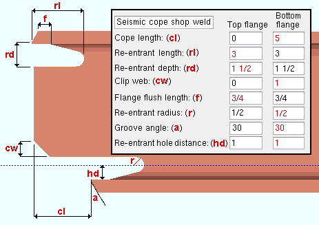
Parametric module: m.Ends[0].TopDimension8 or m.Ends[0].BottomDimension8' Seismic cope shop weld ' gives you distance entry fields for " Cope length ," " Re-entrant length ," " Re-entrant depth " " Clip web " " Flange flush length " " Re-entrant radius " " Groove angle " " Re-entrant hole distance ." Setup: Seismic Weld Access Holes . CNC : " Add holes " in CNC Setup can be set to ' In copes ' or ' In all radii ' to download the weld prep hole.
Advanced Selection: m.Ends[0].TopDimension1 or m.Ends[0].BottomDimension1
Advanced Selection: m.Ends[0].TopDimension2 or m.Ends[0].BottomDimension2
Advanced Selection: m.Ends[0].TopDimension3 or m.Ends[0].BottomDimension3
Advanced Selection: m.Ends[0].TopDimension4 or m.Ends[0].BottomDimension4
Advanced Selection: m.Ends[0].TopDimension5 or m.Ends[0].BottomDimension5
Advanced Selection: m.Ends[0].TopDimension6 or m.Ends[0].BottomDimension6
Advanced Selection: m.Ends[0].TopDimension7 or m.Ends[0].BottomDimension7
Advanced Selection: m.Ends[0].TopDimension8 or m.Ends[0].BottomDimension8Parametric module: m.Ends[0].TopDimension1 or m.Ends[0].BottomDimension1
Parametric module: m.Ends[0].TopDimension2 or m.Ends[0].BottomDimension2
Parametric module: m.Ends[0].TopDimension3 or m.Ends[0].BottomDimension3
Parametric module: m.Ends[0].TopDimension4 or m.Ends[0].BottomDimension4
Parametric module: m.Ends[0].TopDimension5 or m.Ends[0].BottomDimension5
Parametric module: m.Ends[0].TopDimension6 or m.Ends[0].BottomDimension6
Parametric module: m.Ends[0].TopDimension7 or m.Ends[0].BottomDimension7
Parametric module: m.Ends[0].TopDimension8 or m.Ends[0].BottomDimension8
| OK = end operation is applicable to the material type. | ||||||
| 288 = produces failure message 288. | ||||||
| 289 = produces failure message number 289. | ||||||
| ? = may sometimes produce failure message number 289. | ||||||
| W , S | C | L | tube | pipe | WT | |
| Cope plain | OK | OK | OK | OK | OK | OK |
| Cope field #3 | OK | OK | ? | 289 | 289 | ? |
| Cope shop #3 | OK | OK | ? | 289 | 289 | ? |
| Cut flange width | OK | 288 | 288 | 289 | 289 | 289 |
| Cut flange flush | OK | 288 | 288 | 289 | 289 | 289 |
| Clip flange | OK | 289 | 289 | 289 | 289 | 289 |
| Notch top/bottom | 289 | 289 | 289 | OK | OK | 289 |
| Notch NS/FS | 289 | 289 | 289 | OK | OK | 289 |
| Cope field #1 | OK | OK | ? | 289 | 289 | ? |
| Cope shop #1 | OK | OK | ? | 289 | 289 | ? |
| Clip web | OK | OK | OK | 289 | 289 | OK |
| Cope field seismic | OK | OK | ? | 289 | 289 | ? |
| Cope shop seismic | OK | OK | ? | 289 | 289 | ? |
Report Writer: Member.LeftEnd.MoreEnd.TopOrBottomOperations.TopOperationTypeDescription
Report Writer: Member.LeftEnd.MoreEnd.TopOrBottomOperations.BottomOperationTypeDescription
