 Add Void Space Layout ( Modeling )
Tool summary :
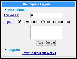
The Void Space Layout becomes a custom component of the member that you select to add it to.
Also see :
|
|
- Modeling (where custom components can be added)
- Custom components (topic)
- Add Component (step-by-step instructions)
- Automatically process after modeling operation ( User and Site Options > Modeling > affects " OK ")
- CMU Opening (alternative for CMU Walls)
- Concrete Wall Opening (alternative for concrete walls)
- Voids ( Display Options )
- Delete key (or choose Edit > Delete to delete a component)
- Copy Component (related tool)
- Move Component (related tool)
- Web Penetration with Stiffeners (another way to add voids)
- Void Space Layout custom member (another way to add voids)
- Void Space Cylinder component (another way to add voids)
- Void Space Cylinder custom member (another way to add voids)
page 1 | contents | model > component > | add component | top
------ ![]() Void settings ------
Void settings ------
Thickness: A positive distance or negative distance (in the primary dimension " Units " or other units ). This sets the depth into the screen or out of the screen that the void will be extruded from the plane in which the layout points were added.
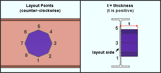
|
| This example shows a counter-clockwise layout on the near side face of a beam. Since t is positive, the thickness of the void is projected into the screen to the far side face of the beam and beyond. . |
A positive distance extends the volume of the void space into your computer screen the distance that is entered if the layout points were added counter-clockwise. If the layout points were added clockwise, a positive distance extends the void space volume in the opposite direction (toward you, the viewer).
A negative distance exends the volume of the void space into your computer screen the distance that is entered if the layout points were added clockwise. If the layout points were added counter-clockwise, a positive distance extends the void space volume in the opposite direction (toward you, the viewer).
Apply to: ![]() all materials or
all materials or ![]() selected materials .
selected materials .
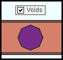
|
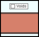
" Voids " is turned on (checked) in Display Options . This void would be displayed as shown regardless of whether the choice made here was ' all materials ' or ' selected materials '. |
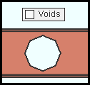
|
" Voids " is turned off (not checked) in Display Options . For the material to be removed by the void as shown here, " Apply to " must be set to ' all materials ' or to ' selected materials ' with the material shown in the list . |
|
" Voids " is turned off (not checked) in Display Options . " Apply to " is set to ' selected materials ', but the main material of the beam shown here is not included in the list . As a result, the material is solid since no material is removed by the void. |
'
all materials ' results in all materials that are associated with the member you added this component to being voided wherever they are impinged upon by the void.
'
selected materials ' lets you select which materials of this component's member you want to be affected by the void. Only those materials that you select by pressing " Add " to place them in the list will be voided when they are impinged upon by the void. For steel materials, the " Weight of item " and " Surface area " reported on the member material's General Information window will be reduced only if those materials are listed.
Example of a "selected materials" list:

When " Apply to " is set to ' selected materials ', only materials assigned pcmk_1 or pcmk_2 or pcmk_3 will have material removed when the void passes through them.
page 1 | contents | model > component > | add component | top
 |
| This Void Space Layout component was added to the near side web of the beam that the void space is a component of. The X member coordiate of the origin point (which coincides with point 1) is 16 feet, 7 inches from the left end of the beam (-16-7). The Y coordinate of that same point is 9 inches down from the top flange of the beam (9). The Z coordinate is 3/16 inch from the center of the web (-3/16). |
Axes: Although the diagram's origin point is expressed in the member coordiates of the member that the void space belongs to, the diagram's coordinate system may or may not coincide with the member coordinate system. In other words, the axes shown in the diagram may or may not be parallel with the member axes.
Radius: A distance (in the primary dimension " Units " or other units ) that defines the degree to which the corner is rounded.
The " Radius " is the radius of a circle. Two lines that are tangent to that circle meet at the located point. The arc of the rounded corner ends at the points of tangency of these two lines. 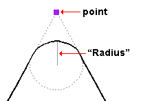
A " Radius " of ' 0 ' designates a sharp corner with no corner rounding.
Increasing the " Radius " moves the edge of the rounded corner back from the corner point. This is because the " Radius " defines a circle that is tangent to both lines to the corner point. The arc of the rounded corner begins and ends at the tangent points.
You can set a different " Radius " for each corner. Clicking on the upper-right corner of the table (" Radius > ") lets you set the radius for each point to be the same value.
' X-Y ' shows the layout points in the flat plane that includes those points. This is typically the best view to see all of a void's layout points.
' X-Z ' shows a elevation view of the layout points in a flat, X-Z plane that is at right angles to (orthogonal to) the Y axis. In such a view, the layout points for a void whose " Z-axis " values are all the same will appear as a single line.
' Y-Z ' shows a elevation view of the layout points in a flat, Y-Z plane that is orthogonal to the X global axis. In such a view, the layout points for a void whose " Z-axis " values are all the same will appear as a single line.
Dimension by: Length and angle or Previous point or Origin point . This applies when you hover a point in the diagram with your mouse pointer ( ![]() ), regardless of whether or not you are adding points.
), regardless of whether or not you are adding points.
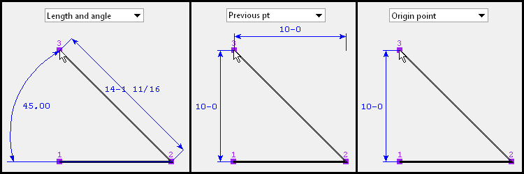
' Length and angle ' shows one or two dimensions and an angle. The dimension(s) are to the point you are hovering. One dimension may be to the previous point, and another dimension may be to the next point. The angle to the point you are hovering may be the included angle between the hovered point and the previous two points. Or it may be the angle between the hovered point and a horizontal or vertical bisector to the previous point.
VIDEO 
" Dimension by " is set to ' Length and angle ' and the distance and angle between points is defined for the first two points. Additional points are defined by clicking instead of typing. ' Previous point ' shows horizontal and/or vertical dimensions between the point you are hovering and the previous point in the diagram. Dimensions of zero will not be shown.
' Origin point ' shows horizontal and/or vertical dimensions from the origin point (point 1) to the point you are hovering. Dimensions of zero will not be shown.
Adding points: You can click a line in the diagram to add a point. The new point snaps to your mouse pointer until you left-click to locate that point or right-click to cancel. Dimensions are shown as you move your mouse pointer to reposition the snapped-to point. An alternative to clicking in the diagram to add points is to enter the points to the table.
page 1 | contents | model > component > | add component | top


