Add CMU Opening ( Modeling )
Tool summary :
On the CMU Wall Edit window, the name of the leaf for the concrete wall opening " Component " will be " CMU Opening. "
You can edit the tabs using the settings under that leaf. Or, to open up this window (shown at left), double-click a CMU Opening material while the " Selection filter " is set to ' Custom Components ''.

- To begin adding the custom component , you can click the Add CMU Opening icon or use Add Component . The icon can be found in the command group ' Model--Component ' for the Ribbon Editor.
- See, on this page, to add, edit or delete the cmu opening custom component .
Also see :
- Modeling (where custom components can be added)
- Custom components (topic)
- Copy Component (to copy a concrete wall opening custom component to another concrete wall or layout)
- Move Component (to move a concrete wall opening custom component to another concrete wall or layout)
- Explode Component (to reduce the custom component to its constituent materials)
- Component Selection Tool (to search for custom components of a selected type)
- Model Tree (to find custom components and select them for deletion, editing, etc.)
- Concrete Wall Opening (a component for adding openings to concrete walls )
To add, edit or delete the CMU Opening custom component :
|
To add the custom component: 1) In Modeling , use Snap to Surface or a related tool to go to a plane that is parallel with a side of the wall. 2) Place construction lines so that there are INCL points at the locations of the top corners of the opening that you will place. 3) Select the wall or layout, so the material changes to the User and Site Options > Modeling > " Primary selection surface color ." 4) Choose Model > Component > Add . 5) On the custom component selection list, choose " CMU Opening " as the custom component you want to add. 6) Select the intersections that you defined in step 2. 7) The CMU Opening window opens. Enter the settings that you want, then press " OK " to close the window. 8) If User and Site Options > Modeling > " Automatically process after modeling operation " is set to ' Process and create solids ', the opening and its reinforcement will be generated immediately. If not, they will be generated on the wall the next time the wall undergoes Process and Create Solids .
Tip: If you use in-tool selection -- that is, select the wall after selecting " CMU Opening " as the custom component you want to add -- only CMU walls will be selectable. To edit a CMU Opening component or review its settings, you can find the wall it is added to and open its edit window. The component's settings will be contained in that window in a section named [ CMU Opening ] . To edit a CMU Opening custom component without opening the Concrete Wall or Concrete Elevation Wall Layout windows, use the Model Tree . You also can use the Selection Filter toolbar item to select the ' Custom Components ' filter and double-click the CMU opening component, or the multi-sided flat plate material in the opening, to edit the component. The Component Selection Tool can also be used to edit (and find) custom components.
To delete a CMU Opening custom component: 1 ) Use the Component Selection Tool and select the component in the member. Or , select the component in the Model Tree . 2 ) Press the Delete key (or choose Edit > Delete ). 3 ) Process and Create Solids if User and Site Options > Modeling > " Automatically process after modeling operation " is not set to a choice that automatically creates solids.
In the Model Tree , the CMU Opening custom component is listed as CMU Opening @ ( [ x, y, z ] ) when " View By " is set to ' Member piecemark ' or ' Member number '. The CMU Opening component is listed under its member, after that member's connection components ( Left End and Right End ), and before that members's submaterials.
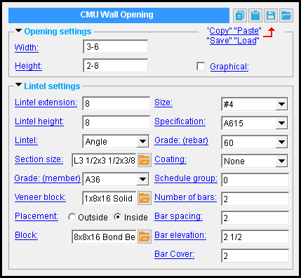
CMU Opening custom component settings :
| CMU Opening |
------  Opening settings ------
Width: A distance (in the primary dimension " Units " or other units ). This is the width of the opening, exclusive of reinforcement.
Initially, the " Width " is the distance between the two points you placed -- indicating the top corner locations -- when you added the component.
If you change the value of this option, the opening will lengthen or shorten on the right side of the component, while the left side will remain stationary.
Height: A distance (in the primary dimension " Units " or other units ). This is the height of the opening, exclusive of reinforcement.
If you change the value of this option, the opening will lengthen or shorten on the bottom side of the component, while the top corners remain stationary.
|
A CMU Opening component is automatically set to "
Graphical " whenever you make graphical changes to any of its materials. For example, when you Edit Material or apply a Cut on Plane operation on a lintel. This stops the component from being changed during Process and Create Solids . Click here for more information.
Instead of allowing the component to be made "
------ Lintel settings ------
Lintel extension: The distance (in the primary dimension " Units " or other units ) by which the lintel extends beyond the left and right edges of the opening. This option applies even when the " Lintel " type is ' None '.
Lintel height: The height (in the primary dimension " Units " or other units ) by which the lintel extends above the top edge of the opening. This option applies even when the " Lintel " type is ' None '.
Lintel: None or Wide flange or Channel or Angle or Bond beam . When the lintel is a member, you must also choose a " Section size ," while a ' Bond beam ' requires a choice of " Block ." When the lintel type is ' None ', a cavity for the lintel is modeled.
You cannot eliminate the lintel by entering a ' 0 ' for either the "Lintel extension" or the "Lintel height" option. If you do, the entries will be invalid and you will not be able to close this window using " OK ."
When the " Lintel " type is ' Wide flange ', ' Channel ', or ' Angle ':
Section size: The wide flange, angle, or channel's main material (e.g., ' W8x10 '). Only materials listed in the local shape file can be specified here.
To enter a section size: You can type in the section size that you want, or you can press the "file cabinet" browse button (
) and double-click any section that is on the list of available materials in the local shape file . Validation only lets you enter a material that is listed in the local shape file and that is the same type as the " Lintel " type.
Grade (member): A36 or A992 or etc . This is the steel grade of the members's main material.
Veneer block: The name of a CMU template . The template you choose should consist of a profile that describes the block from which the veneer is constructed. This option applies when the " Lintel " type is ' Wide flange ' or ' Channel '.
To enter a bond beam size, you can type in the name of the CMU template that corresponds to the veneer block that you want, or you can press the "file cabinet" browse button (
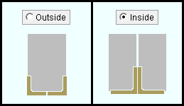
Placement: ![]() outside or
outside or ![]() inside . The location of the two angles within the CMU wall. This option applies when the " Lintel " type is ' Angle '.
inside . The location of the two angles within the CMU wall. This option applies when the " Lintel " type is ' Angle '.
'
outside ' places the angles outside of the " Block ."
'
When " Lintel " type is 'Angle' or ' Bond beam ':
Block: The name of a CMU template . The template you choose should consist of a profile that describes the block from which the lintel is constructed.
To enter a block size : You can type in the name of the CMU template that corresponds to the block that you want, or you can press the "file cabinet" browse button (
When the " Lintel " type is ' Bond beam' :
Size: A reinforcing bar size designation that has been entered to the Rebar Definitions Setup window under the " Active rebar standard ".
Specification: A615 or A706 or etc. This is an ASTM specification entered into the Rebar Specifications window.
The " Steel grade " and " Coating " options are limited to the grades and coating entered into the Rebar Specification window for the selected ASTM specification.
Grade (rebar): 60 or 40 or etc. This is the yield strength (grade) of the reinforcing bar in the bond beam.
The grade choices in this list box are limited to those entered in the Rebar Specification window for the " Specification " chosen for this rebar shape.
Coating: None or a Coating designation that is available in the " Standard " that you have selected.
The coating choices in this list box are limited to those entered in the Rebar Specification window for the " Specification " chosen for this rebar shape.
Select ' None ' if you do not want a coating. Since it is possible to create specifications that do not have coatings, it is possible that ' None ' may be your only option.
User configuration: If a coating is not available for selection, selecting a different " Specification " will make that coating available if the coating you want is in that other standard. If you don't want to change to a different " Specification ," you can open the Rebar Specifications window and add the coating you want to the specification that you currently have selected.
Schedule group: Any non-negative integer with less than ten digits. Your choice of schedule group is not limited by any configuration option. The group applies to this member only -- see special case below.
Reason to assign a schedule group: The output of the Rebar List Report , Rebar in Member Report , and Bend Schedule custom reports can be limited to particular schedule groups. As a result, you can assign rebar shape material to different schedules, and create separate reports for rebar from each schedule.
A special case: You change the schedule group on one of the rebar shapes. If you press " Yes " when prompted " Do you want regenerate... ," the changed schedule group is applied to ALL rebar matching the options checked in the Change All Options window.
User configuration: You can open the Report Manager window or the Table Edit window to copy, create, or edit rebar custom reports. " Edit " the report to add a comma-delimited list of schedule groups that the custom report will select.
Number of bars: This is the number of reinforcing bars in the bond beam channel. The number you enter must be greater than zero.
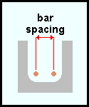
Bar spacing: The on-center distance (in the primary dimension " Units " or other units ) between bars, when the " Number of bars " is greater than one.
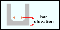
Bar elevation: The distance (in the primary dimension " Units " or other units ) from the bottom of the bond beam (exclusive of grout) to the center of the reinforcing bar.
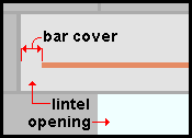
Bar cover: The distance (in the primary dimension " Units " or other units ) on each side from the ends of the bar to the ends of the bond beam.