The Welded Wire Mesh Edit window
| Documentation in progress. |
|
Changes made to a welded wire mesh layout's " Horizontal wire diameter " and " Vertical wire diameter " will update the 3D model. |
Options :
ABM options :

Information on the material you are editing may be included in an ABM when the " ABM " check box is checked.
Add [Legacy] Miscellaneous Member settings :
Once a legacy miscellaneous member is added, these options are shown on the [Legacy] Miscellaneous Member Edit window.
To open this window :
- Add Material
- Add Miscellaneous Member
- Edit One Material (gives change option s)
- Edit Multiple Materials (no change options)
- Double-click the material (to edit a material added using Add Material )
- "Edit Other" (to edit a material added using Add Miscellaneous Member )
- Double-click a material in the Model Tree
- Review 2D Items ( Drawing Editor -- non-editable)
Also see :
- Dimension precision (sets precision for distance entries)
- General Information (can be opened from this window)
- Submaterial piecemark (each unique material identified by)
- submaterial detail (2D drawing of a material)
- Welded Wire Mesh (material)
- Altering a miscellaneous member's main view
page 1 | contents | add material | add miscellaneous member | top
Welded wire mesh layout :
Welded wire mesh may be laid out in a plan view or an elevation view . Make sure that you have construction lines drawn that will aid you in defining the shape you want. These instructions assume that you are using a 3-button mouse.
1 . Welded wire mesh can be added to the 3D model as a submaterial of a member or as a miscellaneous member. Do one (1) of the following:
To add welded wire mesh TO a member (pre-selection method): Select the one (1) member that you want to add the material to (so that it is displayed in the " Primary selection color ") > press F3 > filter for "
Concrete / Rebar " > double-click " Welded Wire Mesh ." Continue to step 2.
To add welded wire mesh AS a new member: Press F2 > filter for "
Miscellaneous steel " > double-click " Miscellaneous -- Welded Wire Mesh ." Continue to step 2.
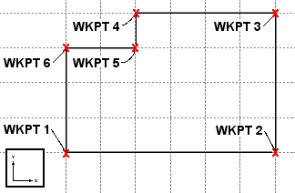
2 . The status line prompts, " Locate point: " Locate-OK-Cancel mouse bindings become active. Select the appropriate Locate option, then place work points as described below. The following illustration shows work points for welded wire mesh laid out in a plan view.

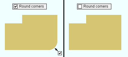
2a : A dialog box for corner rounding opens. As you left-click ( Locate ) to define points, remember to set corner rounding for the most recently located point before you left-click ( Locate ) to define the next point. Below is an example of a mesh layout with rounding applied to a single corner (indicated with an arrow), and also without corner rounding.

2b ( optional ): If you accidentally left-click ( Locate ) at a point you do not want, hold down Shift and middle-click ( Remove ) to remove that point. You can remove as many points as you like, then continue locating points as described in 2a.
2c : Middle-click ( OK ) with your mouse pointer anywhere in the view. This locates the final point exactly where you placed the starting point.
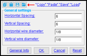
3 . After you have located the material reference point, the Welded Wire Mesh Edit window opens.
1a : " Horizontal spacing " and " Vertical spacing " and " Horizontal wire diameter " and " Vertical wire diameter " are filled out with default settings that match the last welded wire mesh that you added in your current Modeling session. If you did not previously add a mesh, default settings populate this window. You should change these settings as you see fit, then press the " OK " button.
4 . The Rotate Material window opens, and a preview of the new welded wire mesh is shown on screen. Do one (1) of the following:
Alternative 1 : Press " Cancel " to back up to step 2. This stops the wire mesh from being added.
Alternative 2 : To accept the material's present rotation, press the " OK " button.
Alternative 3 : Change the material's rotational settings and then press " OK " if you want to rotate the material.
5 . Different end steps are required depending on whether you are adding a material to a member or adding a stand-alone legacy miscellaneous member.
End steps for adding a material TO a member: After rotating the material into place > locate a material dimension reference point > right-click ( Return ) if done adding material to the member > Change All Options can be applied if the material is being added to a member that is batched together with other members that have the same member piecemark.
End steps for adding a material AS a legacy miscellaneous member: After rotating the legacy miscellaneous member into place > right-click ( Return ) if you are done adding duplicates or variations of the legacy miscellaneous member.
Tip 1: If you added a legacy miscellaneous member (see step 1), you cannot re-open this window using Edit Member -- that opens the [Legacy] Miscellaneous Member Edit window. This is a material window, not a member window, and you therefore have to open it by, for example, using Edit One Material , " Edit Other " on the context menu, or by double-clicking the material in the Model Tree .
Tip 2: If you added this material as a submaterial (see step 1), you can, in addition to the edit methods described in tip 1, double-click the material to re-open this window.
page 1 | contents | add material | add miscellaneous member | top
 " Copy " " Paste " " Save " " Load " buttons :
You'll find buttons like these at the top of this window. They apply to all user-editable settings that are on this window. Click here for more information.
You can " Copy " (
) the settings on this window, then " Paste " (
) those settings to a different welded wire mesh.
" Save " (
) saves a file to the form/WeldWireMesh_GenSettings folder (
) that is used by your current version of SDS2. Give the file a name that will help other users identify its purpose. " Load " (
) copies over all settings on this window with the settings that are stored in the file that you select.
" Paste " and " Load " replace mixed entries to a single field with a single entry. " Copy " and " Save " ignore fields with mixed entries, treating them as if they have no entry or do not exist.
page 1 | contents | add material | add miscellaneous member | top
------ General settings ------
| Defaults: If you press " OK " to close this window, the entries made to these options become the defaults for the next-added welded wire mesh. |
Horizontal spacing: The horizontal distance on center (in the primary dimension " Units " or other units ) between longitudinal (vertical) wires.
Report Writer: MemberMaterial.Material.CustomMaterials.WeldedWireMesh.horz_mesh_dim
Vertical spacing: The vertical distance on center (in the primary dimension " Units " or other units ) between transverse (horizontal) wires.
Report Writer: MemberMaterial.Material.CustomMaterials.WeldedWireMesh.vert_mesh_dim
Horizontal wire diameter: The diameter (in the primary dimension " Units " or other units ) of transverse (horizontal) wires.
Report Writer: MemberMaterial.Material.CustomMaterials.WeldedWireMesh.horz_wire_diam
Vertical wire diameter: The diameter (in the primary dimension " Units " or other units ) of longitudinal (vertical) wires.
Report Writer: MemberMaterial.Material.CustomMaterials.WeldedWireMesh.vert_wire_diam
page 1 | contents | add material | add miscellaneous member | top
To close this window :
" General Information " opens the General Information window, which provides additional information and settings about this welded wire mesh.
Tip: You can use the General Information window to change the material's " X ," " Y ," or " Z " global coordinates (and thus reposition the material within the 3D model).
Also: A " Properties " button at the bottom of the General Information window lets you Edit Properties for this material.
"OK" (or the Enter key) closes this window and applies the settings on it. Even if you did not make any changes on this window, pressing " OK " causes certain " General settings " to be applied as the defaults for the next welded wire mesh that is added next in your current session of Modeling .
"Cancel" (or the Esc key or the ![]() button) closes this window without making any changes to the material.
button) closes this window without making any changes to the material.
Possibilities: If you are performing a Add Material or Add Miscellaneous Member operation, " Cancel " brings you back to the work point location step ( step 2 ) in the add operation. For an Edit Material operation, " Cancel " ends the operation.
Tip: When you open this window to review information only -- and you do not want to set the defaults for the next-added welded wire mesh -- the best way to close this window is to press " Cancel. " Also see the warning under " OK " for another good reason to press " Cancel " instead of " OK ."
"Reset" undoes all changes made to this window since you first opened it. The window remains open.
Note: For an Add Material or Add Miscellaneous Member operation, the " General settings " you get are those of the last-added or last-edited welded wire mesh (unless you exit Modeling in the meantime).
page 1 | contents | add material | add miscellaneous member | top


