Material Type Selection window (for material or misc members in Modeling )
The Material Type Selection window opens when you Model > Material > Add or press F3 . Any type of material that is listed on this window can be added to the 3D model . These material types include:
|
|
||
| Rolled Section | Extruded Profile | |
|
|
||
| Rectangular Plate | Round Plate | Bent Plate |
| Rolled Plate | Flat Plate Layout | Bent Plate Layout |
| Round Bar | Square Bar | Flat Bar |
|
|||||||||
|
|
||
| Existing Material | Grating | Grating Tread |
| Decking | Shear or Threaded Stud | Turned Element |
| Clevis | Turnbuckle | Reference Member |
| Reference Profile Layout | Bolt |
Library Part ( |
| No Paint (Toolbox) | No Paint Layout (Toolbox) | Part Library Fastener |
| Resistor | Tetrahedron | |
page 1 | contents | misc member | material | top
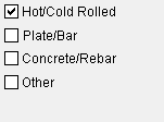
You can select categories of material to show or exclude them from the material selection list. When a category is checked ( ![]() ), material types associated with the category will be shown in the list. Multiple material categories may be checked.
), material types associated with the category will be shown in the list. Multiple material categories may be checked.
|
When the " |
Hot/Cold Rolled :
or
. This includes " Rolled Section ," and " ExtrudedProfile ."
Plate/Bar :
or
. This includes, for example, both " Bent Plate " and " Bent Plate Layout ," as well as " Round... ," " Square... ," and " Flat Bar ."
Concrete/Rebar :
or
. This includes " CMU Material ," " Rebar Layout ," " Shaped Rebar ," and " Welded Wire Mesh ."
Other :
or
. This includes materials not belonging to the other categories; for example, " Grating ," " Decking ," " Clevis ," etc.
page 1 | contents | misc member | material | top
Existing Material . After you choose this item on the Material Type Selection window, a selection dialog opens with a list of submaterial marks . The list includes all submaterials in the model plus any standard piecemarks that are defined in Home > Project Settings but have not yet been added to the model. Double-click the submaterial mark that you want.
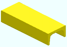
Rolled Section . Choose this option to add to the model a miscellaneous member or submaterial that is a rolled section such as a channel , wide flange , S shape , HSS rectangular , angle or HSS round section.
|
Rolled section material can be a material that is defined in the local shape file except joist and round bar or clevis or turnbuckle. |
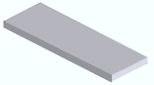
Rectangular Plate . Choose this option to add to the 3D model a rectangular miscellaneous member or submaterial that is plate material .
|
Rectangular plate material can be made into checkered plate . |
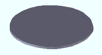
Round Plate . Choose this material type to add to the 3D model a round miscellaneous member or submaterial that is plate material .
|
The default material mark prefix for rectangular , round , rolled and layout plate material is ' p '. |
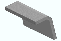
Bent Plate . Choose this material type to add to the 3D model a single-bend miscellaneous member or submaterial that is plate material . To add plate material with multiple bends, use Bent Plate Layout .
|
The default material mark prefix for bent plate and bent plate layout is ' bp '. |
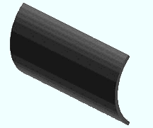
Rolled Plate . Choose this material type to add to the 3D model a curved miscellaneous member or submaterial that is plate material .
|
Steel grades that are available for plate material are set up using Home > Project Settings > Job > " Plate Grades ." |
Flat Plate Layout . Choose this material type to create a flat plate layout miscellaneous member or submaterial to the 3D model (example: floor plate around members or equipment).

|
This flat plate layout was created by locating a point at each of the plate's 11 vertices. |
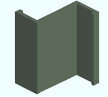
Bent Plate Layout . Choose this material type to create a miscellaneous member or submaterial with multiple bends from plate material . When you lay out multi-bend plate submaterial, you are looking at its thickness.
|
Here's a bent plate layout that has four bends. |
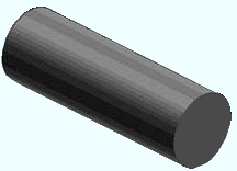
Round Bar . Choose this material type to add a miscellaneous member or submaterial made of round bar material .
|
Round bar is defined in the local shape file to facilitate its use for rod bracing . |
Square Bar . Choose this material type to add a miscellaneous member or submaterial made from square bar stock .
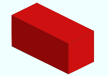
|
Steel grades that are available for square bar, round bar and flat bar material are defined at Home > Project Settings > Job > Material Grades > " Round and Square Bar Grades ." |
Flat Bar . Choose this material type to add a miscellaneous member or submaterial made of flat bar .
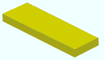
Grating. Choose this material type to add a grating miscellaneous member or submaterial to the 3D model. Grating is composed of vertical and horizontal bars with end bands on either end.
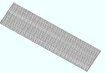
Grating Tread. Choose this material type to create a rectangular grating tread miscellaneous member or submaterial . Like grating, this is a composite material made of horizontal and vertical bars. In addition, grating tread has end plates and nosing.
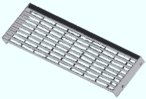
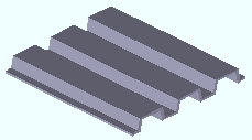
Decking. Choose this material type to create a rectangular decking miscellaneous member or submaterial . Decking material is steel of uniform thickness that has been bent to form ribs. Decking or "form deck" is used for stay-in-place forms for structural concrete slabs, but is also used without concrete. It may be used in roof construction.
Assembly. Choose this option to add an assembly to the 3D model. The version of this window ( Material Type Selection ) that opens when you press F3 does not have a selection for ' Assembly '.
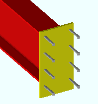
Shear or Threaded Stud . Choose this material type to add a shear stud or threaded stud miscellaneous member or submaterial to the 3D model.
|
Shear studs welded to an embed plate. |
Turned Solid/Shell Element . Select this option to lay out points for the generation of a solid/shell element legacy miscellaneous member or submaterial from a two-dimensional figure that you draw on screen.

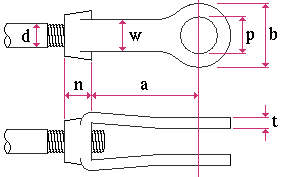
Clevis . Clevis material must be in your local shape file in order for you to be able to add a clevis miscellaneous member or submaterial . Use the Shapes Properties or the Copy Shapes utility to add clevis material if there currently is no such material in the local shape file. Shape file settings for clevis material are illustrated below.
|
d = max tap diameter w = width p = max pin diameter b = outside diameter t = thickness n = tap grip a = inside to pin center |
Turnbuckle . Turnbuckle material must be in your local shape file in order for you to be able to add a turnbuckle miscellaneous member or submaterial . Use the Shapes Properties or the Copy Shapes utility to add turnbuckle material if there currently is no such material in your local shape file. Shape file settings for turnbuckle material are illustrated below.

|
d = rod diameter n = hole length a = inside length e = inside width g = width |
|
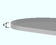
t = the thickness of the reference member. In this example, the reference member is used to represent a concrete slab. |
|
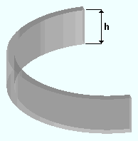
h = the height of a reference profile layout used to represent a concrete wall. |
Bolt . This may be selected as the material type when you Add Material or Add Miscellaneous Member . Bolt materials are just like bolts, except that a " Piecemark " can be assigned to them. Also, you can perform various material operations on material bolts that you cannot perform on regular bolts. You cannot perform bolt operations on material bolts.

Library Part . Library parts are stored in the data directory used by your current version of this program. Storage of these libarary parts is managed using the Part Library Manager . When a library part is added in Modeling , you select the part on the Part Library window, its link to the Part Library is severed, and it is copied into the model as a standard part . Even if you delete the original library part, its copy remains in the model as a standard part. Like any other material, a library part that has been added to the model can be auto detailed. On member details, the library part's weight, quantity and description may be listed in the bill of material.
|
No Paint : Choose this option to add no paint areas to members. When the member is auto detailed, these areas are shown in the Drawing Editor with dashed lines and may be labeled with "NO PAINT" or other text. Adding a no paint area is similar to adding " Flat Bar ." However:
No Paint Layout : Adding a no paint layout is similar to adding " Flat Plate Layout ." Such layouts resemble no paint areas, insofar as it is a " User created material " that is added with an SDS2 Toolbox tool.
Part Library Fastener : This works much like " Library Part ," except as follows:
- Only library parts whose " Part type " is ' Fastener ' can be selected on the Part Library Fastener Edit window. You select a part from that window by pressing the
 button next to " Part name ."
- A part library fastener that is properly set up using the Part Library Manager produces a bill of material description that is fastener appropriate.
- You also, on the Part Library Fastener Edit window, have the option to set the fastener's " Class " to ' Field ' or ' Shop '.
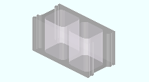
CMU Material adds a legacy miscellaneous member or submaterial made of CMU material . The member's profile will be defined by a CMU template .
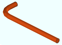
Rebar Layout . Choose this option to lay out points for the generation of a legacy miscellaneous member or submaterial made of rebar shape material . The points you lay out will be matched to a rebar shape template . Alternatively, you may use the layout points to create a new rebar shape template.
Shaped Rebar . This works similarly to Rebar Layout , but requires the selection of a rebar shape template that has already been created. You may add the rebar by selecting the points required by the template. Alternatively, you may select the ends of reinforcing bar dowels. If necessary, you may create new rebar templates in the Rebar Shape Template Editor .
|
Rebar shape material is used by both Rebar Layout and Shaped Rebar . |
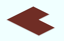
Welded Wire Mesh . Choose this material type to add to the 3D model a legacy miscellaneous member or submaterial from welded wire mesh material . Welded wire mesh material is a flat region of welded wire reinforcement with irregular edges.
|
This welded wire mesh region was created by locating a point at each of the mesh's 6 vertices. |
page 1 | contents | misc member | material | top
