The Rolled Plate Material window ( Modeling ) (read-only)
Also see :
- General Information window (opened from this window)
- Submaterial piecemark (each unique material identified by)
- Submaterial detail (2D drawing of a material)
- Plates
page 1 | contents | material review | material types
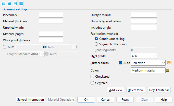
------ General settings ------
Piecemark: The submaterial piecemark ( up to 61 characters ) for the rolled plate whose settings you are reviewing.
Note: Rolled plate system piecemarks begin with the piecemark prefix for " Plate ." For the current quantity of rolled plates that have been assigned this piecemark, refer to the " Current quantity " listed for this rolled plate on its General Information window.
Material thickness: The thickness of the rolled plate being reviewed (in the primary dimension " Units " or in other units or the gage ). Thickness is the dimension along the plate's Z material axis .
Gage plate: If, for example, ' 4GA ' is entered here, then this is a gage plate. Allowable gages are any whole number from 3 to 38 . The " Description " for a gage plate follows the format: ' plate type prefix ' + ' numberGA ' + ' x ' + ' width ' (example: PL16GAx15 1/2 ).
Unrolled width: The material width (in the primary dimension " Units ") when the plate is laid flat (unrolled).
The " Unrolled width " is calculated from the rolled plate's " Outside radius " and " Included angle " and on the choice made to " Rolled plate width dimension taken from " in Detailing Criteria (setup). The " Unrolled width " is used in the material " Description " found on the General Information window and in the " Description " in the member bill of material. The " Unrolled width " of the plate is also included in the plate section callout on the plate's submaterial detail .
Material length: The length (in the primary dimension " Units " or in other units ) of the rolled plate along its longitudinal axis ( X material axis ).
Note: If the only operations performed on this material are the entry of an " Outside radius " and an " Included angle ," the distance shown here will be the same as the " Work point distance ."
Work point distance: The distance (in the primary dimension " Units " or in other units ) between the work points of this rolled plate.
Note: In most cases, the distance shown here will be the same as the " Material length ." However, in the case of a tapered rolled plate (where a value for " Outside tapered radius " has been entered), this distance will be different from the " Material length ."
Outside radius: The distance (in the primary dimension " Units " or in other units ) from the outside corner the rolled plate to the center of an imaginary circle extrapolated from the outside edges of the rolled plate.
Visualizing the outside radius: Imagine that you are looking at the end of the rolled plate where the first work point was located; you would see a cross-section of the width of the rolled plate (its Y material axis ). Extrapolate an arc from the outside curvature of the bend on the rolled plate, then measure the distance from either end of that arc to the center of the imaginary circle which that arc is a part of.
Outside tapered radius: 0 or a distance (in the primary dimension " Units " or in other units ) specifying the radius of the rolled plate from the end opposite to the first work point.
' 0 ' (zero) or the exact same distance entered to " Outside radius " means the rolled plate is not tapered.
A ' distance ' (other than that entered to " Outside radius ") means the rolled plate is tapered.
Included angle: Any angle from .1 to 360 degrees.
This is the number of degrees of the circle that is taken up by the arc of the outside face of the rolled plate (the radius of this arc is the " Outside radius "). The entry shown here directly affects the " Unrolled width " of the rolled plate.
Fabrication method: Continuous rolling or Segmented bending .
' Continuous rolling ' indicates that the curve of the rolled plate is smooth, continuous and parabolic.
' Segmented bending ' means the rolled plate is a series of flat (not-curved) bend segments that together approximate a parabola. The number of segments is the number entered to " Bend segments ."
Bend segments: 0 or a quantity of segments from 3 to 400 .
' 0 ' (zero) produces the same result as " Continuous rolling ."
An entry of ' 3 or greater ' applies when " Segmented rolling " is selected. The more the segments, the smaller the bend angle between each segment, and the more closely the rolled plate approximates a continuous parabolic curve.
Steel grade: Any grade of steel ( A36 or A572 or etc.) from the Steel Grades for Plates & Bar Stock table may be shown here as the steel grade of this rolled plate.
Surface finish: None or Sandblasted or Red oxide or Yellow zinc or Gray oxide or Blued steel or Galvanized or Duplex Coating or Undefined 1 or Undefined 2 or Undefined 3 or Red oxide 2 or Any user added surface finish. This affects the colors of 'Solid ' members on erection views in the Drawing Editor . This also sets the color when "Output material color " is set to 'Surface finish ' for a VRML Export or a DWG/DXF Export . The "Color " ( not "Surface finish ") sets the color of this material in Modeling .
| sand blasted | red oxide | yellow zinc | user surface finish 1 |
| gray oxide | blued steel | galvanized | user surface finish 2 |
To assign a different surface finish, you can drop-down the current surface finish and select the one you want, or you can press the "file cabinet" browse button (
) and double-click any surface finish that is on the list.
Auto ![]() or
or ![]() .
.
If this box is checked (
), the material surface finish follows what is set on the member level.
If the box is not checked (
), the material surface finish can be changed to whatever is available in the list of surface finishes. If the surface finish changes from what the member level has set, the auto checkbox will be unchecked automatically. When the auto check box is unchecked, the member edit window shows an information tag which notifies the user that an attached material is not following what was set on the member level.
Note 1: Submaterial piecemarks can be split apart by surface finish. All surface finishes that do not have the 'Break Marks Material' checked on can be applied to any like material with out the material splitting. If the 'Break Marks Material' is checked on then only like materials with that specific surface finish can have the same piecemark, and because the submaterial marks differ so would the member's piecemark.
Note 2:When exporting a KISS file using "model" as the "Data source " surface finish data on the materials are compiled into the KISS download as follows, with a few exceptions (G=galvanized, N= none or sandblasted, P= others). Those exceptions are:
If the box for "Finish" routing in KISS export setup is set to a user routing
If the user has adjusted the Abbreviation for any of the default provided surface finishes
If you are using a user added surface finish
In these cases you will get what is provided in either the User routing, or the abbreviation field. For other exports it will always provide the abbreviation in the 'surface finishes' settings page.
Tip 1: "Surface area" is reported on the General Information window -- and this can be used to estimate the amount of coating required and its cost.
Tip 2: Changing "Steel grade " "Color " and "Surface finish " do not cause the plate to be regenerated. This means that, if you change those settings only, material fit operations such as a Fit Exact may, optionally, be preserved.
Report Writer:MemberMaterial.Material.SurfaceFinish
Setup:Surface Finish Settings
Color: The color of the rolled plate when it is displayed in solids form . Different colors may be assigned to materials that have the same submaterial piecemark . The color swatch next to the list box ( ![]() ) displays the color that is selected.
) displays the color that is selected.
Setup: The default colors for member main materials and submaterials is set up on the Modeling Colors setup window.
If this box is checked (
If the box is not checked (
Centered: ![]() or
or ![]() . This option positions the rolled plate with respect to its reference point . The first work point located when this rolled plate was added sets the position of the reference point.
. This option positions the rolled plate with respect to its reference point . The first work point located when this rolled plate was added sets the position of the reference point.
If this box is checked (
If the box is not checked (
page 1 | contents | material review | material types | top
To close this window :
![]()
![]()
" General Information " opens the General Information window, which you can use to review additional information about the selected material.
Pressing " Close " on the General Information window to close that window and reactivate this window.
"OK" (or the Enter key) closes this window.
page 1 | contents | material review | material types | top