 Embed
Embed
- General Overview
- Step-By-Step
- Tips and Tricks
- Related Tools
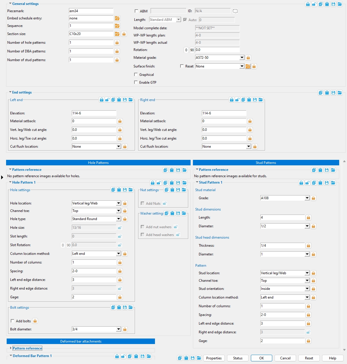
General Settings
Piecemark: Blank or a system piecemark or a user-entered string (of up to 61 characters ) which identifies this angle or channel embed member as having an unique design distinct from other members that have been assigned different piecemarks. This is the member piecemark of the embed member.
Blank indicates that SDS2 piecemarking will assign a system piecemark to the embed member when you press OK to close this window. Piecemark is left blank when you first add a new angle or channel embed.
A system piecemark (system piecemark) is the piecemark that SDS2 piecemarking has assigned.
A user piecemark is a user-entered string. SDS2 piecemarking will not assign new members that user piecemark, nor will piecemarking remove that user piecemark from members to which it has been assigned. It is your responsibility to ensure that the same user piecemark is not used for another distinctly different member.
Tip: You can get rid of a user piecemark that has been assigned to an embed member by clearing the Piecemark entry and leaving the field blank. When you press OK, SDS2 piecemarking routines will automatically assign a system piecemark to the member.
Embed schedule entry: A standard piecemark name from the Piecemark column in the Embed Schedule.
Sequence: Any sequence name from the Sequence Names setup list can be entered here.
To assign a different sequence, you can type in any sequence name that is on the Sequence Names list, or you can press the ![]() browse button and double-click any sequence name that is on the list.
browse button and double-click any sequence name that is on the list.
Defaults: The sequence assigned by default to the first embed angle or channel member that is added after you first start up Modeling is the sequence listed in line 1 of the Sequence Names list. For each subsequent angle or channel embed member that you add during the same session in Modeling, the sequence that is assigned by default is the sequence assigned to the last-added or last-edited member.
Section size: Any section for angle or channel materials that are listed in the local shape file.
If Section size
is unlocked, the section size shown here is the Section size in Job > Connections > Embed Schedule that is entered for the selected Embed schedule entry.
If Section size
is locked, you can enter a different section size. Either type in the section size that you want, or you can press the
browse button and double-click any section that is on the list of available materials in the local shape file. If the new section size you enter no longer matches the corresponding entry made to the schedule, when you press OK and SDS2 piecemarking evaluates your change, a new Piecemark may be assigned.
Number of hole patterns: The quantity of hole patterns. To change the number, you can alter the Embed schedule entry, or you can ![]() lock the Number of hole patterns.
lock the Number of hole patterns.
0 results in there being no leaf for
Hole Pattern on this window.
1 or more results in one or more leaves on this window.
Job > Connections > Embed Schedule: Number of hole patterns
Number of DBA patterns: The quantity of DBA patterns. To change the number, you can alter the Embed schedule entry, or you can ![]() lock the Number of deformed bar attachments.
lock the Number of deformed bar attachments.
0 results in there being no leaf for Deformed Bar Pattern on this window.
1 or more results in one or more leaves on this window.
Job > Connections > Embed Schedule: Number of DBA patterns
Number of stud patterns: The quantity of Stud patterns. To change the number, you can alter the Embed schedule entry, or you can ![]() lock the Number of stud patterns.
lock the Number of stud patterns.
0 results in there being no leaf for
1 or more results in one or more leaves on this window.
Job > Connections > Embed Schedule: Number of stud patterns
Model complete date: **NOT SET** or a month day year (see entering dates ).
**NOT SET** removes the designation of Model complete from this embed member, thus allowing the member to be physically altered. Type 0 to enter **NOT SET** -- see entering dates.
If a month day year is entered, settings on this window are grayed out and cannot be changed. The affected embed member is prevented from being altered during the solids creation phase of Process and Create Solids.
WP-WP length: plan: Read-only. The work point-to-work point distance spanned by the angle or channel embed's member line in a plan view, ignoring elevation. This distance is calculated from the X and Y (but not Z) global coordinates of the embed member's work points.
Note: For an embed member that is sloping, this distance is different than the WP to WP length: actual. Both distances are automatically calculated from the work points that you located when you added the member.
WP-WP length: actual: Read-only. The actual length of this angle or channel embed member's member line. This distance is calculated from the X and Y and Z global coordinates of the angle or channel embed member's work points.
For an embed with square cut ends, subtracting the left and right Material setback from the WP-WP length: actual gives you the length of the embed material.
Rotation: A positive or negative number of degrees greater than -180 ° or less than or equal to 180°. This controls the rotation of an embed angle or channel about its member line.
|
An embed shown in an elevation view. The member line of the embed is horizontal. That is, both its left Elevation and right Elevation are the same. |
Material grade: A36 or A572 or etc. This is the Steel grade of the angle or channel material that is used to fabricate the embed.
If Material grade
Job Setup: If the grade of steel you want is not shown on the list box, you can use Home > Project Settings > Job > Material Grades > Channel Grades or Angle Grades to add it to the list.
Surface finish: None or Sandblasted or Red oxide or Yellow zinc or Gray oxide or Blued steel or Galvanized or Duplex Coating or Undefined 1 or Undefined 2 or Undefined 3 or Red oxide 2 or Any user added surface finish. This affects the colors of Solid members on erection views in the Drawing Editor. This also sets the color when Output material color is set to Surface finish for a VRML Export or a DWG/DXF Export.The Color (not Surface finish) sets the color of this material in Modeling.
| sand blasted | red oxide | yellow zinc | user surface finish 1 |
| gray oxide | blued steel | galvanized | user surface finish 2 |
Reset : ![]() or
or ![]()
If this box
is checked, all attached materials' surface finish are reset to follow what is selected on the member level, with the check box checked on for auto inside of the material edit window, when the window is closed by selecting the OK button (or the Enter key).
If the box
is not checked, all attached materials' surface finish remains at what is set inside the material edit window.
Note 1: If the material surface finish changes from what the member level has set, an information tag is shown next to the surface finish in the member edit window. This notifies the user that an attached material has been changed by a user from what was set on the member level.
Note 2:Member Piecemarks can be split apart by surface finish. All surface finishes that do not have the Break Marks Member checked on can be applied to any like member with out the member splitting. If the Break Marks Member is checked on then only like members with that specific surface finish can have the same piecemark.
Graphical: ![]() or
or ![]()
If Graphical
If Graphical
Warning: Any graphical changes that you make to materials will be preserved only so long as the custom member is set to
If this box
If the box
Long leg direction (angle): Vertical or Horizontal. This applies when the Section size is an angle with unequal legs.
|
|
If Long leg direction
End Settings
Elevation: The elevation of the work point at this end of the angle or channel embed.
Material setback: The positive or negative distance that you want the (left or right) end of the embed to be displaced from its work point.
A positive material setback makes the embed material shorter. For an embed with square cut ends, subtracting the left and right Material setback from the WP-WP length: actual gives you the length of the embed material.
A negative (-) material setback makes the rolled section longer. Subtracting a negative left and right Material setback from the Work point distance increases the Order length.
Vert leg / Web cut angle: A positive or negative number from 89 to -89 degrees.
| channel or angle embed | ||||
| left | right | left & right | left | right |
-10 degrees
 |
-10 degrees
 |
0 degrees
 |
10 degrees
 |
10 degrees
 |
An entry of 0 (zero) designates that no web cut be made. Assuming that you are on the near side of the web of the material, a positive angle is measured counterclockwise from a perpendicular bisector to the member line; a negative (-) angle is measured clockwise from a perpendicular bisector to the member line.
Horz leg / Toe cut angle: A positive or negative number from 89 to -89 degrees.
| angle or channel embed | ||||
| left | right | left & right | left | right |
-10 degrees
 |
-10 degrees
 |
0 degrees
 |
10 degrees
 |
10 degrees
 |
An entry of 0 designates no flange cut. Assuming that the left end of the embed is to your left, a positive angle is measured counterclockwise from a perpendicular bisector to the back of the angle or channel. A negative (-) angle is measured clockwise from a perpendicular bisector to the back of the angle or channel.
Cut flush location: Vertical leg / Web or Horizontal leg / Toe or Both legs / Toe and web.
|
elevation views |
|
plan views |
Vertical leg / Web gives you distance-entry options for setting the Cut radius and Cut length dimensions. For an angle embed, the vertical leg is cut flush to the horizontal leg. For a channel embed, the bottom toe and web are cut flush to the top toe. Cut length runs parallel with the length of the embed.
Horizontal leg / Toe also gives you distance-entry options for setting the Cut radius and Cut length dimensions. If the embed is a channel, you can also specify the Toe to cut as Top or Bottom or Both. For an angle embed, the horizontal leg is cut flush to the vertical leg. For a channel embed, the selected toe(s) are cut flush to the web.
Both legs / Toe and web z combines the functionality of the other two options.
Hole Pattern
Hole location: Vertical leg / Web or Horizontal leg / Toe or Both legs / Toe and web.
Vertical leg / Web locates the hole pattern on the vertical leg of an angle embed, the web of a channel embed.
Horizontal leg / Toe locates the hole pattern on the horizontal leg of an angle embed, the top toe of a channel embed.
Both legs / Toe and web locates the hole pattern on both legs of an angle embed. For a channel embed, it locates the pattern at the Channel toe location and the web of a channel embed.
If Hole location
Channel toe: Top or Bottom or Both. This applies to channel embeds only.
Top specifies that the Hole location and Gage apply to the top channel toe.
Bottom specifies that the Hole location and Gage apply to the bottom channel toe.
Both specifies that the Hole location and Gage apply to both channel toes.
Hole type: Standard round or Short slot or Oversized round or Long slot or Cope hole or Erection pin hole or Anchor bolt hole or Plug weld hole or Grout or Vent/Drain.

If Hole type
Hole size: read-only. The hole size that is reported here is calculated automatically based on the Hole type and the Bolt diameter.
Slot length: read-only. The slot length that is reported here depends on the Hole type and the Bolt diameter. For hole types other than Long slot or Short slot, the reported slot length is always 0.
Column location method: Left end or Right end or Both ends or Fixed edge distance or Fixed spacing.
Left end puts the Number of columns of holes in the embed. The first hole is placed at the Left end edge distance from the left end of the embed, and additional holes are placed from left to right at the Spacing distance from that first left-end hole.
Right end puts the Number of columns of holes in the embed. The first hole is placed at the Right end edge distance from the right end of the embed, and additional holes are placed from right to left at the spacing distance from that first right-end hole.
Both ends adds twice the Number of columns of holes on the embed. The left-end hole group begins at the Left end edge distance from the left end of the embed. The right-end hole group begins at the Right end edge distance from the right end of the embed. The left-end hole group is spaced from left to right, beginning at the left-end hole per the Spacing, which can be variable. The right-end hole group is spaced per that same spacing, but from right to left beginning with the right-end hole.
Fixed edge distance puts holes the outermost holes at the Left end edge distance and Right end edge distance from their respective ends. The holes that are interior to those outermost holes are evenly spaced the Spacing distance from one another. The center line of the pattern is half-way between the left edge distance and the right edge distance.
Fixed spacing places the first hole at the Left end edge distance from the left end of the embed, then spaces each subsequently placed hole the Spacing distance from the previously placed hole. The last hole is placed so that it is to the left of (or exactly at) the Right end edge distance.
If Column location method
Number of columns: The count of columns of holes. This applies when the Column location method is Left end or Right end or Both ends. This option is disabled grayed outwhen the Column location method is Fixed edge distance or Fixed spacing.
If the Column location method is Left end or Right end, this is the total number of holes that are placed in the specified Hole location.
If the Column location method is Both ends, this is half the total number of holes that are placed in the specified Hole location.
If Number of columns
Spacing: A center-to-center distance or variable spacing.
Spacing (center-to-center) is the distance between holes in the hole pattern when the Column location method is Left end, Right end, or Fixed spacing. When the Column location method is Fixed edge distance, a single distance entry specifies the center-to-center distance between interior holes in the pattern. For Both ends, you get two hole patterns, and the distance entry is the center-to-center distance between holes that are in the same pattern.
Spacing (variable) can apply when the Column location method is Left end or Right end or Both ends. Variable spacing does not override the Number of columns Variable spacing does not apply to the Fixed spacing or Fixed edge distance column location methods.
Variable Spacing Spacing Result 2-0,3-0,2-0 3 spaces at 2 ft, 3 ft, and 2 ft 3@2-0 3 spaces at 2 ft If Spacing
Left end edge distance: The distance from the left edge of the embed to the leftmost hole in the hole pattern when the Column location method is Left end or Both ends or Fixed edge distance or Fixed spacing. If the Column location method is Right end, no hole is placed closer to the left end than this distance.
If Left end edge distance
Right end edge distance: The distance from the right edge of the embed to the rightmost hole in the pattern when the Column location method is Right end or Both ends or Fixed edge distance. If the Column location method is Left end or Fixed spacing, no hole is placed closer to the right end than this distance.
If Right end edge distance
Gage: A distance. This applies when the Hole location is Vertical leg/ Web or Horizontal leg / Toe or Both legs / Toe and web. It applies to angle or channel embeds.
For a channel embed, the Gage is the distance from the top of the channel to the center of the web hole when Hole location is set to Vertical leg/ Web. When the Deformed bar location is set to Horizontal leg / Toe, this is the distance from the heel of the channel to the center of the hole in the top toe in the channel.
For a angle embed, the Gage is the distance from the top of the angle to the center of the hole in the vertical leg when Hole location is set to Vertical leg/ Web. When the Hole location is Horizontal leg / Toe, this is the distance from the back of the angle to the center of the hole in the horizontal leg.
If Gage
Bolt settings
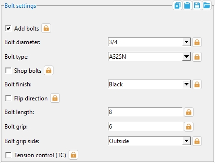
Add bolts: ![]() or
or ![]() This applies to angle or channel embeds with a hole pattern.
This applies to angle or channel embeds with a hole pattern.
If this box
If the box
If Add bolts
Bolt diameter: The diameter of the shank of the bolt. This applies even if you have not elected to Add bolts since the diameter that you enter here together with the Hole type sets the Hole size.
| diameter |
|
If Bolt diameter
Bolt Edit: Diameter
Bolt type: A325N or A325SC or A490N, etc. The bolt types that you can choose in the list box are the bolt types that are listed at Home > Project Settings > Job > Bolts, Washers, and Holes > Bolt Specifications.
If Bolt type
Bolt Edit: Bolt type
If this box
If the box
If Shop bolts
Bolt finish: Black or Zinc/Aluminum ASTM F1136 or Mechanically galvanized or Hot dipped galvanized.
Note: When the member's surface finish is Galvanized, you must select Mechanically galvanized or Hot dipped galvanized as the Bolt finish.
If Bolt finish
If this box
If the box
Bolt length: The distance from the inside of the bolt head to the end of the bolt shank.
If Bolt length
Bolt grip: The distance between the face of the embed to the inside of the bolt head (or nut). If the bolt has washers, the bolt grip is measured from the inside of the washers.
If Bolt grip
Bolt grip side: Inside or Outside.
Inside puts the bolt to the inside of the angle or channel embed.
Outside puts the bolt to the outside of the angle or channel embed.
If Bolt grip side
If this box
If the box
If Tension control
Nut settings
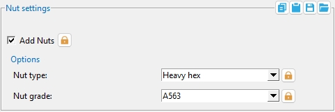
Add nuts: ![]() or
or ![]() This applies to embeds with a hole pattern for which
This applies to embeds with a hole pattern for which ![]() Add bolts is turned on. A primary heavy hex nut is assumed to be attached to a bolt and, therefore, its prescience or absence is not automatically called out in the member bill of material.
Add bolts is turned on. A primary heavy hex nut is assumed to be attached to a bolt and, therefore, its prescience or absence is not automatically called out in the member bill of material.
If this box
If the box
If Add nuts
|
Nut grade: Any grade that has been entered to the Nuts tab at Home > Project Settings > Job > Bolts, Washers, and Holes > Nut and Washer Schedule. If you want other grades to appear, you need to add them to the Nut and Washer Schedule under the appropriate nut type (Heavy hex).
If Nut grade
Washer settings
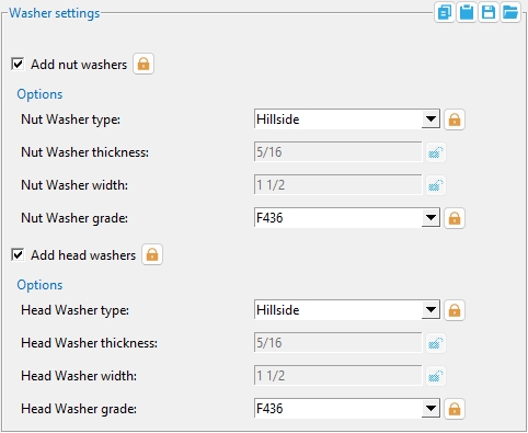
Add nut washers: ![]() or
or ![]() This applies to embeds with a hole pattern for which
This applies to embeds with a hole pattern for which ![]() Add bolts is turned on.
Add bolts is turned on.
If this box
If the box
If Add nut washers
Nut washer type: Bevel or Square plate or Round plate or Direct tension indicator or Hillside or Flat or Hardened.
| type | shape | BOM |
| bevel |
|
BVL |
| square plate |
|
PL |
| round plate |
|
RPL |
| direct tension indicator |
|
DTI |
| hillside |
|
HLS |
| flat |
|
FL |
| hardened |
|
HD |
If Nut washer type
Nut washer thickness: The thickness of the square plate or round plate washer.
t = thickness
If Nut washer thickness
Nut washer width: The length or width of a square plate washer, or the diameter of a round plate washer.
w = width
If Nut washer width
Nut washer grade: Any grade that has been entered to the Washers tab at Home > Project Settings > Job > Bolts, Washers, and Holes > Nut and Washer Schedule for the selected type (Hardened or Bevel or etc.) can be selected. Note that when you switch to a different Nut washer type, different grades are shown.
If Nut washer grade
Add head washers: ![]() or
or ![]() This applies to embeds with a hole pattern for which
This applies to embeds with a hole pattern for which ![]() Add bolts is turned on.
Add bolts is turned on.
If this box
If the box
If Add head washers
Head washer type: Bevel or Square plate or Round plate or Direct tension indicator or Hillside or Flat or Hardened.
| type | shape | BOM |
| bevel |
|
BVL |
| square plate |
|
PL |
| round plate |
|
RPL |
| direct tension indicator |
|
DTI |
| hillside |
|
HLS |
| flat |
|
FL |
| hardened |
|
HD |
If Head washer type
Head washer thickness: The thickness of the square plate or round plate washer.
t = thickness
If Head washer thickness
Head washer width: The length or width of a square plate washer, or the diameter of a round plate washer.
w = width
If Head washer width
Head washer grade: Any grade that has been entered to the Washers tab at Home > Project Settings > Job > Bolts, Washers, and Holes > Nut and Washer Schedule for the selected type (Hardened or Bevel or etc.) can be selected. Note that when you switch to a different Head washer type, different grades are shown.
If Head washer grade
Deformed Bar attachments
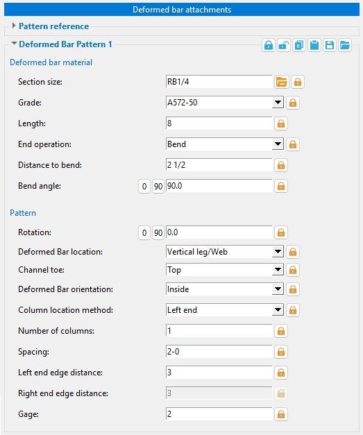
Deformed bar material
Section size: Any round bar Section size that is maintained in the local shape file.
If Section size
Grade: Any steel grade that is available at Home > Project Settings > Job > Material Grades > Round and Square Bar Grades can be selected here.
If Grade
Length: The actual length when DBA when the End operation is None. For DBAs with an End operation of Hook or Bend, the actual unbent length of the DBA will be larger than this Length.
If Length
End operation: None or Hook or Bend.
None specifies a DBA that is straight.
Hook specifies a hooked DBA that is modeled based on the Hook type that is specified below.
Bend specifies a bent DBA with a bend that begins at the Distance to bend. The angle of the bend is the Bend angle.
If End operation
Hook type: 180 or 90 or - 90 or -180.
If End operation
Distance to bend: The distance from the surface of the embed to the bend.
If Distance to bend
Bend angle: A positive or negative number of degrees. A negative sign (-) sets the direction of the bend to be opposite to an equivalent entry with no negative sign.
If Bend angle
Pattern
Rotation: A positive or negative (-) number of degrees from -180 to 180. Each of the DBAs in the pattern are rotated by this amount.
If Rotation
Deformed bar location: Vertical leg / Web or Horizontal leg / Toe or Both legs / Toe and web or Corner, 45 degrees.
Vertical leg / Web locates the DBAs on the vertical leg of an angle embed, the web of a channel embed.
Horizontal leg / Toe locates the DBAs. on the horizontal leg of an angle embed, the top toe of a channel embed.
Both legs / Toe and web locates the DBAs on both legs of an angle embed. For a channel embed, it locates the pattern at the Channel toe location and the web of a channel embed.
Corner, 45 degrees locates the DBAs to the interior corner of the angle embed when Deformed bar orientation = Inside. It locates them on the outside corner of the angle embed when Deformed bar orientation = Outside. On a channel embed, this applies only to the top corner of the channel.
If Deformed bar location
Deformed bar orientation: Inside or Outside.
Inside puts the DBAs to the inside of the angle or channel embed.
Outside puts the DBAs to the outside of the angle or channel embed.
If Deformed bar orientation
Channel toe (channel): Top or Bottom or Both. This applies to channel embeds only.
Top specifies that the Stud location and Stud orientation and Gage apply to the top channel toe.
Bottom specifies that the Stud location and Stud orientation and Gage apply to the bottom channel toe.
Both specifies that the Stud location and Stud orientation and Gage apply to both channel toes.
Column location method: Left end or Right end or Both ends or Fixed edge distance or Fixed spacing.
Left end puts the Number of columns of DBAs on the embed. The first DBA is placed at the Left end edge distance from the left end of the embed and each additional DBA is placed from left to right at the Spacing distance from that first DBA until the total number of DBAs is equal to the number of columns.
Right end puts the Number of columns of DBAs on the embed. The first DBA is placed at the Right end edge distance from the right end of the embed and each additional DBA is placed from right to left at the Spacing distance from that first right-end DBA until the total number of DBAs is equal to the number of columns.
Both ends adds twice the Number of columns of DBAs to the embed. The left-end DBA group begins at the Left end edge distance from the left end of the embed. The right-end DBA group begins at the Right end edge distance from the right end of the embed. The left-end DBA group is spaced per the Spacing distance from left to right beginning at the left-end DBA. The right-end DBA group is spaced per that same Spacing distance, but in the opposite direction, from the right-end DBA.
Fixed edge distance puts the outermost DBAs at the Left end edge distance and Right end edge distance from their respective ends. The DBAs that are interior to those outermost DBAs are spaced the Spacing distance from one another. The number of spaces for the interior DBAs is determined by dividing the distance between the outermost DBAs by the Spacing distance. The center line of the pattern is half-way between the left edge distance and the right edge distance. If the number of spaces for the interior DBAs is an even number, a DBA is placed at the center line of the pattern. If the number of spaces is an odd number, the center of the middle space aligns with the center line of the pattern. Variable Spacing and Number of columns do not apply.
Fixed spacing places the first DBA at the Left end edge distance from the left end of the embed, then spaces each subsequently placed DBA the Spacing distance from the previously placed DBA. The last DBA is placed so that it is to the left of (or exactly at) the Right end edge distance. Variable Spacing and Number of columns do not apply.
If Column location method
Number of columns: The count of columns of DBAs. This applies when the Column location method is Left end or Right end or Both ends. This option is disabled (grayed out) when the Column location method is Fixed edge distance or Fixed spacing.
If the Column location method is Left end or Right end, this is the total number of DBAs that are placed in the specified Deformed bar location.
If the Column location method is Both ends, this is half the total number of DBAs that are placed in the specified Deformed bar location.
Spacing: A center-to-center distance or variable spacing.
Spacing (center-to-center) is the distance between DBAs in the pattern when the Column location method is Left end, Right end, or Fixed spacing. When the Column location method is Fixed edge distance, a single distance entry specifies the center-to-center distance between interior DBAs in the pattern. For Both ends, there are two DBA patterns, and the distance entry is the center-to-center distance between DBAs that are in the same pattern.
Spacing (variable) can apply when the Column location method is Left end or Right end or Both ends. Variable spacing does not override the Number of columns. Variable spacing does not apply to the Fixed spacing or Fixed edge distance column location methods.
Variable Spacing Spacing Result 2-0,3-0,2-0 3 spaces at 2 ft, 3 ft, and 2 ft 3@2-0 3 spaces at 2 ft If Spacing
Left end edge distance: The distance from the left edge of the embed to the leftmost DBA in the pattern when the Column location method is Left end, Both ends, Fixed edge distance, or Fixed spacing. If the Column location method is Right end, no DBA is placed closer to the left end than this distance.
If Left end edge distance
Right end edge distance: The distance from the right edge of the embed to the rightmost stud in the pattern when the Column location method is Right end, Both ends, or Fixed edge distance. If the Column location method is Left end or Fixed spacing, no stud is placed closer to the right end than this distance.
If Right end edge distance
Gage: A distance. This applies when the Deformed bar location is Vertical leg/ Web or Horizontal leg / Toe or Both legs / Toe and web.

For a channel embed, the Gage is the distance from the top of the channel to the center of the DBA when Deformed bar location is set to Vertical leg/ Web. When the Deformed bar location is set to Horizontal leg / Toe, this is the distance from the heel of the channel to the center of the DBA.
For a angle embed, the Gage is the distance from the top of the angle to the center of the DBA when Deformed bar location is set to Vertical leg/ Web. When the Deformed bar location is Horizontal leg / Toe, this is the distance from the back of the angle to the center of the DBA.
If Gage
Stud Pattern
Stud material
Stud grade: A108 or A493 or etc. This is the grade of steel for all of the shear studs that are a part of this pattern.
If Stud grade
Setup: If the grade of steel you want is not shown, you can use Home > Project Settings > Job > Material Grades > Shear and Threaded Stud Grades to add it to this list.
Stud dimensions
Length: The distance between the two ends of the embed's shear studs. The head is included in the length of a shear stud.
l = length 
If stud Length
Warning: Do not change the Stud length of embed shear studs on the Shear or Threaded Stud Material window -- change the Length here instead.
Diameter: The diameter of the shafts of the embed's shear studs. T
d = diameter If stud Length
Warning: Do not change the Stud diameter of an embed's shear studs on the Shear or Threaded Stud Material window -- change the Stud diameter here instead.
Stud head dimensions
Thickness: The distance between the top of the head and the lower edge of the head. Enter a stud head Length of 0 to get shear studs without heads.
ht = head thickness 
If stud head Thickness
Diameter: The diameter of the shear stud's head. Making this the same as the stud Diameter results in shear studs without heads.
hd = head diameter If stud head Diameter
Pattern
Stud location: Vertical leg / Web or Horizontal leg / Toe or Both legs / Toe and web or Corner, 45 degrees. This applies to angle and channel embeds when the Number of stud patterns is 1 or greater.
Vertical leg / Web locates the studs on the vertical leg of an angle embed, the web of a channel embed.
Horizontal leg / Toe locates the studs on the horizontal leg of an angle embed, the top toe of a channel embed.
Both legs / Toe and web locates the studs on both legs of an angle embed. For a channel embed, it locates the pattern at the Channel toe location and the web of a channel embed.
Corner, 45 degrees locates the studs on the interior corner of the angle embed when Stud orientation = Inside. It locates them on the outside corner of the embed when Stud orientation = Outside. On a channel embed, this applies only to the top corner of the channel.
If Stud location
Channel toe (channel): Top or Bottom or Both. This applies to channel embeds only.
Top specifies that the Stud location and Stud orientation and Gage apply to the top channel toe.
Bottom specifies that the Stud location and Stud orientation and Gage apply to the bottom channel toe.
Both specifies that the Stud location and Stud orientation and Gage apply to both channel toes.
Stud orientation: Inside or Outside.
Inside puts the studs to the inside of the angle or channel embed.
Outside puts the studs to the outside of the angle or channel embed.
If Stud orientation
Column location method: Left end or Right end or Both ends or Fixed edge distance or Fixed spacing.
Left end puts the Number of columns of studs on the embed. The first stud is placed at the Left end edge distance from the left end of the embed and each additional stud is placed from left to right at the Spacing distance from each subsequently placed stud until the total number of studs is equal to the number of columns.
Right end puts the Number of columns of studs on the embed. The first stud is placed at the Right end edge distance from the right end of the embed and each additional stud is placed from right to left at the Spacing distance from that first right-end stud until the total number of studs is equal to the number of columns.
Both ends adds twice the Number of columns of studs to the embed. The left-end stud group begins at the Left end edge distance from the left end of the embed. The right-end stud group begins at the Right end edge distance from the right end of the embed. The left-end stud group is spaced per the Spacing distance from left to right beginning at the left-end stud. The right-end stud group is spaced per that same Spacing distance, but in the opposite direction, from the right-end stud.
Fixed edge distance puts the outermost studs at the Left end edge distance and Right end edge distance from their respective ends. The studs that are interior to those outermost studs are spaced the Spacing distance from one another. The number of spaces for the interior studs is determined by dividing the distance between the outermost studs by the Spacing distance. The center line of the pattern is half-way between the left edge distance and the right edge distance. If the number of spaces for the interior studs is an even number, a stud is placed at the center line of the pattern. If the number of spaces is an odd number, the center of the middle space aligns with the center line of the pattern. Variable Spacing and Number of columns do not apply.
Fixed spacing places the first stud at the Left end edge distance from the left end of the embed, then spaces each subsequently placed stud the Spacing distance from the previously placed stud. The last stud is placed so that it is to the left of (or exactly at) the Right end edge distance. Variable Spacing and Number of columns do not apply.
If Column location method
Number of columns: The count of columns of studs. This applies when the Column location method is Left end or Right end or Both ends. This option is disabled (grayed out) when the Column location method is Fixed edge distance or Fixed spacing.
If the Column location method is Left end or Right end, this is the total number of studs that are placed along the length of the embed at the specified Stud location.
If the Column location method is Both ends, this is half the total number of studs that are placed along the length of the embed at the specified Stud location.
Spacing: A center-to-center distance or variable spacing.
Spacing (center-to-center) is the distance between studs in the stud pattern when the Column location method is Left end, Right end, or Fixed spacing. When the Column location method is Fixed edge distance, a single distance entry specifies the center-to-center distance between interior holes in the pattern. For Both ends, you get two hole patterns, and the distance entry is the center-to-center distance between holes that are in the same pattern.
Spacing (variable) can apply when the Column location method is Left end or Right end or Both ends. Variable spacing does not override the Number of columns Variable spacing does not apply to the Fixed spacing or Fixed edge distance column location methods.
Variable Spacing Spacing Result 2-0,3-0,2-0 3 spaces at 2 ft, 3 ft, and 2 ft 3@2-0 3 spaces at 2 ft If Spacing
Left end edge distance: The distance from the left edge of the embed to the leftmost stud in the pattern when the Column location method is Left end or Both ends or Fixed edge distance or Fixed spacing. If the Column location method is Right end, no stud is placed closer to the left end than this distance.
If Left end edge distance
Right end edge distance: The distance from the right edge of the embed to the right edge of the stud pattern. If the Column location method is Right end or Both ends or Fixed edge distance or Fixed spacing, one (or two) studs are centered in line with this location. This edge distance is not applicable when the Column location method is Left end.
If Right end edge distance
Gage: A distance. This applies when the Stud location is Vertical leg/ Web, Horizontal leg / Toe, or Both legs / Toe and web.
For a channel embed, the Gage is the distance from the top of the channel to the center of the stud when Stud location is set to Vertical leg/ Web. When the Stud location is set to Horizontal leg / Toe, this is the distance from the heel of the channel to the center of the stud.
For a angle embed, the Gage is the distance from the top of the angle to the center of the stud when Stud location is set to Vertical leg/ Web. When the Stud location is set to Horizontal leg / Toe, this is the distance from the back of the angle to the center of the stud.
If Gage
![]() Copy, Paste, Save, Load buttons:
Copy, Paste, Save, Load buttons:
- The position of these "form" buttons on the window tells you what settings they apply to. Click here for more information.
- You can
 Copy the settings on this window, then
  Paste those settings to a different edit window of the same type.
- You can
 Save the settings on this window to a file stored in a global folder that is used by your current version of SDS2. Give the file a name that will help other users identify its purpose. You can
  Load a saved file to replace the settings on this window (except Piecemark) with the settings that are stored in the file you select.
- When editing multiple windows at the same time, Paste and Load replace mixed entries to a single field with a single entry. Copy and Save ignore fields with mixed entries, treating them as if they have no entry or do not exist.
Properties opens the Edit Properties window, on which you can make entries to custom properties.If your current Job was set to use a legacy flavor when it was created, the window that opens is named Custom Properties, not Edit Properties.
Tip: The Edit Properties window can also be used to read
Tip: The Member Properties command is an alternative to this button. It opens the Edit Properties window directly, without your first having to open a member edit window.
Status opens the Member Status Review window, which can give you additional information about the member, and which you can use to enter status information or designate a member as an existing member.
Note: This button shows
if one or more Repeat check boxes on the Member Status Review window do not match the checked-unchecked state of same-named fields in User and Site Options > Site > Member status items to copy/repeat. On the Status Review window, the fields that do not match User and Site Options are plotted in red.
OK (or the Enter key) closes the edit window and saves any changes you have made on the window to the member file.
Solids on OK : If the appropriate choice is made to User and Site Options > Modeling > Automatically process after modeling operation, then this member will automatically be regenerated (Create Solids will take place) after your press OK. Otherwise, you will have to manually Process and Create Solids in order for changes you made on this window to be fully updated in the 3D model.
Change all: If you Edit Member (one member only) and make a change that potentially triggers the "Do you want to change all ..." dialog and the 3D model contains more than one member of the same type that has the same piecemark as the member you changed, a yes-no dialog opens. On it is the question, "Do you want to change all (members with this piecemark)" Press the Yes button to change all the members; press the No button to change only this member.
Cancel (or the Esc key or the ![]() button) closes the edit window without saving any changes that you have made.
button) closes the edit window without saving any changes that you have made.
Tip: Any time you use Edit Member just to review a member (and you do not want to set the defaults for to-be-added members), the best way to close this window is to Cancel.
Reset undoes any changes made since you opened this window.
By supporting member's end
1. Click the Embed icon, which is pictured above. The icon can be found on the Members page > Embed section.
Alternative: Invoke Embed using the Find Tool by searching the command name and clicking the icon, which is pictured above.
Learn more about alternative methods for launching commands.
2.The Select add method window opens. Select by supporting member's end and press OK.
3. The status line prompts, Select supporting beam(s) and/or joist(s). Select the beam(s) or joist(s) and press enter or right-click (OK).
Alternative: Right-click (Return) or press the Esc button to end the operation.
4. The status line prompts, Select end(s) on member. Select the left end, right end, or both ends and press enter or right-click (OK).
Alternative: Right-click (Return) or press the Esc button to end the operation.
5. The Embed Edit window opens. After you are done changing or reviewing settings, left-click on the OK button to finish adding the embed members to the selected end(s).
Alternative: Left-click the Cancel button to stop the embed member from being added to the model.
By selecting end-points or mid-point
1. Click the Embed icon, which is pictured above. The icon can be found on the Members page > Embed section.
Alternative: Invoke Embed using the Find Tool by searching the command name and clicking the icon, which is pictured above.
2.The Select add method window opens. Select by selecting end-points or mid-point and press OK.
3. The status line prompts, Embed: Locate top-left corner or mid-point. Various Locate options become active along with Locate - Repeat - Return mouse bindings.
Select the Locate icon you want. Place the ![]() point location target where you want the first work point of the embed, then left-click (Locate).
point location target where you want the first work point of the embed, then left-click (Locate).
Alternative: Right-click (Return) or press the Esc button to end the operation.
4. The status line prompts, Embed: Locate top-left corner or mid-point. Place the ![]() point location target where you want the second work point of the embed, then left-click (Locate). This sets the length of the embed.
point location target where you want the second work point of the embed, then left-click (Locate). This sets the length of the embed.
Alternative: Right-click (Return) to set the first selected point as the midpoint of the embed.
5. The Embed Edit window opens. After you are done changing or reviewing settings, left-click on the OK button to finish adding the embed member.
Alternative: Left-click the Cancel button to stop the embed member from being added to the model.
- This tool is just one of many that you can use for adding embed angles or channels. For each of those methods that create an embed channel or angle, you can edit that plate using the Embed Edit window.
-
 Red-colored highlighting identifies an entry that is invalid. Unless you change that entry, you will not be able to close the entry window using OK.
Hover your mouse cursor over the icon to make a tooltip appear with more information.
Red-colored highlighting identifies an entry that is invalid. Unless you change that entry, you will not be able to close the entry window using OK.
Hover your mouse cursor over the icon to make a tooltip appear with more information.
- Custom members
- Embed Schedule
- Embed Plate
- Embed Layout Add Tool
- Beam to concrete bearing connections
- Shear connection to an embed in a concrete wall
- Clip angle to an embed in a concrete wall
- Beam seat to an embed in a concrete wall
- Joist top chord to concrete with pocket & bearing plate
- Top chord joist seat to an embed
- Extended joist bottom chord stabilizer to an embed

