 No Paint ( Modeling )
Tool summary :
- A no paint area consists of a dummy material. As such, it is not on any member's bill of material, nor can it be downloaded to a CNC file. Detail Submaterial cannot detail dummy material. Furthermore, this material has no " Weight when identified on the General Information window. Its only purpose is to create an area on a member detail suitable for annotation.
General Information , OK , Cancel , Reset


Red-colored highlighting identifies an entry that is invalid. You need to change that entry, or you will not be able to close this window using " OK ."
Also see :
- No Paint Layout (an alternative to No Paint )
- Show paint stripe on framing side of shear plates (can show a no paint symbol per-drawing)
- Show paint stripe on framing side of shear plates (a setup option)
page 1 | contents | material type selection | toolbox
 " Copy " " Paste " " Save " " Load " buttons :
- You'll find buttons like these at the top of this window. They apply to all user-editable settings that are on this window. Click here for more information.
- You can " Copy " (
 ) the settings on this window, then " Paste " (
  ) those settings to a different no paint area.
- " Save " (
 ) saves a "form" file to the
  form/NoPaintRectPlateMtrl_GenSettings folder that is used by your current version of this program. Give the form a name that will help other users identify its purpose. " Load " (
  ) copies over all settings on this window with the settings that are stored in the file that you select.
- " Paste " and " Load " replace mixed entries to a single field with a single entry. " Copy " and " Save " ignore fields with mixed entries, treating them as if they have no entry or do not exist.
page 1 | contents | material type selection | toolbox | top
Overview :
- The No Paint tool's icon can be taken from the group named ' Model -- Material ' and placed on a toolbar (classic) or the ribbon (lightning). It is available at no additional cost to SDS2 software users whose support accounts are current. For more information, contact your SDS2 sales representative.
page 1 | contents | material type selection | toolbox | top
Step-by-step instructions
To add a no paint area to a member (pre-selection method):
1 . Select the one (1) member that you want to add the material to (so that it is displayed in the " Primary selection color ")
2 . Fress F3 . The Material Type Selection window opens. Double-click " No Paint ." (Hint: filter for " ![]() Other .")
Other .")
3 . Locate two material work points by left-clicking ( Locate ). Locating these points should be done in a view whose work plane is orthogonal to (at right angles to) the material being added. (If you have previously entered a no paint area in your current Modeling session, you can left-click twice at the same point to enter a duplicate area of the same length as the original.)
4 . The No Paint Edit window opens. Here, you can make entries to change the area's length and width, and set options that affect auto detailing.
5 . The Rotate Material window opens. Rotate the no paint area into place as required.
6 . Possibly, the Material Add window opens if members that are like the member to which you are adding the material exist in your current Job. Check the box for one or the other of its options to apply the material to other like members.
page 1 | contents | material type selection | toolbox | top
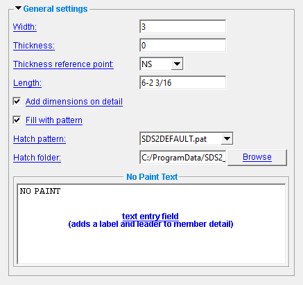
------ General settings ------
Width: The width (in the primary dimension " Units " or other units ) of the no paint area being added/edited. It is permissible to enter a material width dimension that is longer than the no paint area's length.
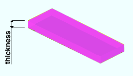
Thickness: The thickness (in the primary dimension " Units " or other units or the gage ) of the no paint area being added/edited. Entering a ' 0 ' creates material with no thickness.
To enter gage material: Type in the ' gage number' followed by ' ga '. The gage you enter is rewritten using the primary dimension " Units " when you Tab out of the field (example: using imperial units, ' .10ga ' becomes ' 1/8 ' when you Tab out of the field). Allowable gages are any whole number from 3 to 38 .
Thickness reference point: FS or Center or NS . ' FS ' stands for far side, ' NS ' for near side. This option orients the " Material thickness " of the no paint area with respect to its workline.
|
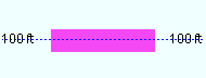
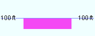
|||
| A section view of the same no paint area, but with different depth reference points. The view looks perpendicular to the plan view (at 100 ft) in which the area was added. |
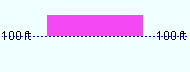
' Center ' aligns the thickness of this no paint area so that it is centered with respect to the area's work points.
' FS ' aligns the area so that its far side surface includes its workline. The far side is the face that is away from you when you are in the view in which the no paint area was added, assuming the area was added by locating two different points and was not subsequently rotated. You might select this setting, for example, when your work plane is the Surface of a material, you have located two points on that surface to add this area, and you want this area's far side to be flush to that surface.
Choose ' NS ' if you added the no paint area in a plan view and want its near side to be at the elevation of the area's work points. The near side is the face of the area that faces you when you are in the view in which it was added, assuming the area was added by locating two different points and was not subsequently rotated.
Note: This option does not change the no paint area's reference elevation. It only changes the positioning of the area with respect to that reference elevation. You can change a no paint area's " Reference elevation " using the General Information window.
Length: The distance (in the primary dimension " Units " or other units ) from the furthest point on the no paint area's left end to the furthest point on the material's right end.
| This material's left end is the end where the first work point of the material was located. This first work point is also this material's 0,0,0 point in the material coordinate system. The point is identified by the origin reference point symbol at the beginning of a Material Rotate operation. |
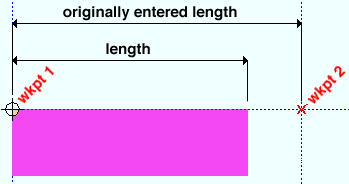
Note: The length entered by the user to this field is added to/subtracted from the end of the no paint area opposite to the first point located .
|

If this box is checked (
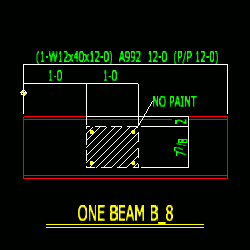
), member detailing with templates is instructed to dimension the no paint area on the member detail.
If the box is not checked (
), the no paint area is not dimensioned.
|
If this box is checked (
If the box is not checked (
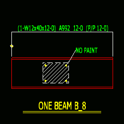
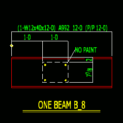
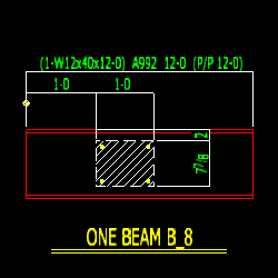
NOTE: The no paint area's " Thickness " is never hatched -- only the opposing faces described by the material's " Width " and " Length ."
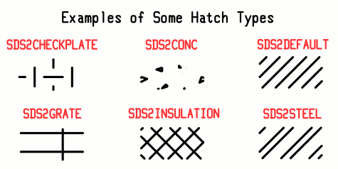
Hatch pattern: A .pat file. For example, SDS2CHECKPLATE or SDS2CONC or SDS2DEFAULT or SDS2GRATE or SDS2INSULATION or SDS2STEEL , which are some of the patterns that are installed into the ![]() hatches folder of data directory used by your current version of this program. This applies when " Fill with pattern " is checked. Choosing a different " Hatch folder " changes the list of patterns to those contained in that folder.
hatches folder of data directory used by your current version of this program. This applies when " Fill with pattern " is checked. Choosing a different " Hatch folder " changes the list of patterns to those contained in that folder.
Hatch folder: A directory (file folder) from which the " Hatch pattern " is chosen. If the folder contains .pat files, their names are used to populate the " Hatch pattern " list.
is a button that lets you select any folder that is accessible from your computer.
page 1 | contents | material type selection | toolbox | top
Entering text to the " No Paint Text " field instructs member detailing with templates to add a label containing that text and a leader when the member is auto detailed. If this field is left empty, neither text nor leader is generated.
|

page 1 | contents | material type selection | toolbox | top
To close the No Paint window :


" General Information " opens the General Information window, which provides additional information and settings that pertain to the material of the no paint area..
Tip: You can use the General Information window to change the material's " X ," " Y ," or " Z " global coordinates (and thus reposition the material within the 3D model).
Also: A " Properties " button at the bottom of the General Information window lets you Edit Properties for this material.
"OK" (or the Enter key) closes the No Paint Edit window and applies the settings on it to the material(s).
Defaults: Even if you did not make any changes on this window, pressing " OK " causes certain " General settings " to be applied as the defaults for the no paint area that is added next in your current session of Modeling .
If you opened this window to edit a single no paint area ( single-edit ), the Change All Options & Warning List opens after you press the " OK " button. You can use that window to cancel your changes or, if other materials with the same submaterial piecemark exist, apply your changes to those other materials. Also, if an Exact Fit or related cutting/bending/fit operation has been done on this no paint area (one no paint area), pressing " OK " gets you the option to undo that operation.
"Cancel" (or the Esc key or the
button) closes this window without saving any changes that you might have made to it.
Tip: When you open this window to review information only -- and you do not want to set the defaults for the next-added no paint area -- the best way to close this window is to press " Cancel. "
"Reset" undoes all changes made to this window since you first opened it. The window remains open.
Note: The settings shown on this window when it first opens for the adding of a no paint area are the settings of the last-added or last-edited no paint area (unless you exit Modeling in the meantime).
page 1 | contents | material type selection | toolbox | top