 Exporting a PML file
- General Overview
- Step-By-Step
- Related Tools
Select Members for PML File window
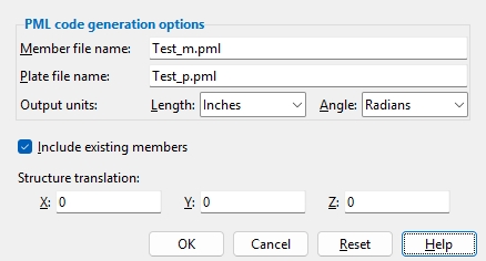
Member file name: The name (filename.pml -- up to 61 characters) of the PML file to which you want to write data on members contained in the SDS2 model.
Plate file name: The name (filename.pml -- up to 61 characters) of the PML file to which you want to write data on plates contained in the SDS2 model.
Length: inches or feet or millimeters or meters . Select the output units that you want all distance data associated with members and plates to be converted into in the PML plate and member files.
Angle: radians or degrees . Select the angle units that you want all distance data associated with members and plates to be converted into in the PML plate and member files.
Include existing members: ![]() or
or ![]() . If this box
. If this box ![]() is checked and your current Job has existing members, these members will be included in the PML file for members. If the box
is checked and your current Job has existing members, these members will be included in the PML file for members. If the box ![]() is not checked, existing members will not be included.
is not checked, existing members will not be included.
Structure translation: 0 or a +/- distance. Use this setting to shift the coordinates of every member by a specific distance in X, Y, and/or Z in the PML plate and member files.
A positive distance is added to the X, Y and/or Z coordinates of all exported members.
A negative distance is subtracted from the X, Y and/or Z coordinates of all exported members.
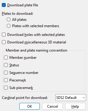
Download plate file:
![]() or
or ![]() . If this box
. If this box ![]() is checked, a plate file will be generated. If the box is not checked (
is checked, a plate file will be generated. If the box is not checked ( ![]() ), only a member file will be generated.
), only a member file will be generated.
Plates to download: All plates or Plates with selected members . Select All plates if you want all plate information in the 3D model to be output. Select Plates with selected members if you only want data for plates that are submaterials of the particular members you selected in step 6.
Download holes with selected plates:
![]() or
or ![]() . This applies when the box for Download Plate File is checked. If this box
. This applies when the box for Download Plate File is checked. If this box ![]() is checked, hole data will be included as part of the plate data. If the box is not checked (
is checked, hole data will be included as part of the plate data. If the box is not checked ( ![]() ), hole data will not be included with the plate data. Tip:Export Model writes hole data fairly quickly. However, importing plates with holes usually takes longer than importing plates without holes. Ask the person who will be importing this data if they want the plates to include holes.
), hole data will not be included with the plate data. Tip:Export Model writes hole data fairly quickly. However, importing plates with holes usually takes longer than importing plates without holes. Ask the person who will be importing this data if they want the plates to include holes.
Download miscellaneous 3D material:
![]() or
or ![]() . Miscellaneous materials are materials that are not included in the local shape file or that are not flat plates. For example, bent plate , square bar , round bar , flat bar , rolled plate , stair treads , grating , grating tread , decking , turned solid/shell elements are miscellaneous 3D materials. If this box
. Miscellaneous materials are materials that are not included in the local shape file or that are not flat plates. For example, bent plate , square bar , round bar , flat bar , rolled plate , stair treads , grating , grating tread , decking , turned solid/shell elements are miscellaneous 3D materials. If this box ![]() is checked, each face of the miscellaneous materials will be defined as a thin plate and downloaded to the plate file. If the box is not checked (
is checked, each face of the miscellaneous materials will be defined as a thin plate and downloaded to the plate file. If the box is not checked ( ![]() ), miscellaneous 3D materials will not be included in the file.
), miscellaneous 3D materials will not be included in the file.
Member and plate naming convention
Member number and/or Status and/or Sequence number and/or Piecemark and/or Submaterial piecemark . These options determine the name (piecemark) used to identify material in the PML file(s) generated. The name is truncated if it exceeds 24 characters.
Cardinal point for download: SDS2 default or 1 or 2 or etc. This applies to straight rolled section or plate members only; it does not apply to curved or bent members. If you do not wish to use the SDS2 Default, then select the cardinal point on the member's section profile that corresponds to the workline of the member.
Note: For a column, the SDS2 Default is cardinal point 5. For a beam, the SDS2 Default is cardinal point 8.
OK (or the Enter key) closes this screen and applies the settings.
Cancel (or the Esc key) closes this screen without saving any changes.
Reset undoes all changes made to this screen since you first opened it. The screen remains open.
1. Click the Export Model icon, which is pictured above. The icon can be found on the Import/Export page > Model section.
Method 2: Click Export Model on the home screen. The command can be found on the Export tab in the 3D section. Skip step 2.
Alternative: Use the Find Tool by searching the command name and clicking the Export Model icon, which is pictured above.
Learn more about alternative methods for launching commands.
2. The status line prompts Select members, and the Select - Pan - Menu mouse bindings become active. Select the member(s), then press Enter or right-click and select OK.
Alternative: Press the Esc key or right-click and select Cancel to end the command.
3. The Export Model window opens. Select PML code generator as the Export file format. Set the Destination where you want the file to be sent. Directory outputs the file to a folder. Select Properties to open the PML Properties window (as shown on the General Overview tab). Select OK.
4. Select the members to download. The Select members for PML files window opens, choose the data you want to include in the download.
5. Select OK, the .pml file is exported.
Alternative: Press the Esc key or select Cancel to end the command.

