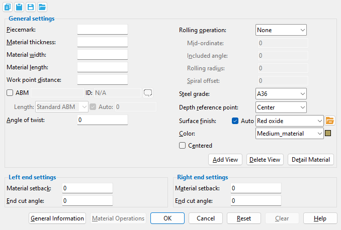
The Flat Bar Material window ( Modeling )
- See (on another page): Adding a flat bar material or legacy miscellaneous member .
- When a legacy miscellaneous member is first added, Add [Legacy] Miscellaneous Member options are shown on this window.
- To open this window (in Modeling ):
- Add a flat bar material or legacy miscellaneous member
- Edit One Material (gives change options)
- Edit Multiple Materials (no change options)
- Double-click the material (to edit a material added using Add Material )
- "Edit Other" (to edit a material added using Add [Legacy] Miscellaneous Member )
- Double-click a material in the Model Tree
- Review 2D Items ( Drawing Editor -- non-editable)
Also see :
- Flat bar miscellaneous member
- Model completed (can make this window read-only)
- Force flat bar description to use smaller of length & width (setup option)
- Dimension precision (sets precision for distance entries)
- General Information window (accessible from this window)
- Submaterial piecemark (each unique material identified by)
- Submaterial detail (2D drawing of a material)
- Flat bar material (type of material this window specifies)
- Grayed out fields (indicate mixed entries or that the field is disabled)
- Altering a legacy miscellaneous member's main view
 " Copy " " Paste " " Save " " Load " buttons :
- You'll find buttons like these at the top of this window. They apply to all user-editable settings (except " Piecemark ") that are on this window. Click here for more information.
- You can " Copy " (
 ) the settings on this window, then " Paste " (
  ) those settings to a different flat bar.
- " Save " (
 ) saves a "form" file to the
  form/flat-bar folder that is used by your current version of this program. Give the form a name that will help other users identify its purpose. " Load " (
  ) copies over all settings on this window (except " Piecemark ") with the settings that are stored in the file that you select.
- " Paste " and " Load " replace mixed entries to a single field with a single entry. " Copy " and " Save " ignore fields with mixed entries, treating them as if they have no entry or do not exist.
------ General settings ------
| Defaults: If you press " OK " to close this window, the entries made to " Material thickness ," " Material width ," " Angle of twist ," " Rolling operation ," " Steel grade ," " Centered ," " Surface finish " and " Color " become the defaults for the next-added flat bar. |
Piecemark: Blank or any character string (up to 61 characters). This is the submaterial piecemark .
If this field is left ' blank ', then when this material is generated (after you press " OK "), SDS2 piecemarking looks for materials in the current Job that are physically identical to this material and assigns to this material the same mark assigned to those materials. If no matching materials are found, piecemarking assigns this material a piecemark using the appropriate piecemark prefix listed in Home > Project Settings > Fabricator > Member and Material Piecemarking > the " Prefixes " tab..
Any ' character string ' that you enter must be unique. Validation does not let you enter a piecemark that has already been assigned to materials. If you are adding a flat bar material or legacy miscellaneous member, a piecemark entered here only applies if the material you are adding is unique -- if the material is exactly the same as previously added materials, the new material gets the piecemark of those previously added materials. On the other hand, if you are editing the material, all materials that are exactly like the material are re-assigned the unique mark you enter when the material is generated (after you press " OK "). The piecemark you enter remains a system piecemark , which means that it may be changed if you later edit a material just like this one and give that material a different piecemark.
Tip: If you want to change a submaterial mark, you should use Rename Project Items in Utility Options . That way all references to the submaterial mark are changed throughout the your current Job, even in Drawing Editor drawings.
Note 1: A submaterial mark is not yet assigned when this window opens for an add material or add legacy miscellaneous member operation. A piecemark is shown when you Edit Material or Review 2D Items . For the current quantity of materials assigned this piecemark, see the " Current quantity " listed on this material's General Information window.
Note 2: Two flat bars may have the same submaterial mark , but different submaterial mark index numbers , when any of the following settings are different: " Depth reference point " " Centered " " Left/Right end settings ."
Report Writer: MemberMaterial.Material.MinorMark
Advanced Selection: MinorMark
Parametric module: MinorMark
Material thickness: The thickness (in the primary dimension " Units " or other units or the gage ) of the bar stock being added/edited. This dimension is measured along the flat bar's Z material axis .
To enter gage material: Type in the ' gage number' followed by ' ga ' (example: ' 4ga ' is rewritten as ' 4GA ' when you Tab out of the field). Right-click tells you the stored thickness (based on industry standards), from which the weight of the gage material is calculated. Allowable gages are any whole number from 3 to 38 . You can also enter an exact decimal thickness to get the gage (example: ' .1345 ' becomes ' 10GA ' when you Tab out of the field). The " Description " for a gage flat bar follows the format: ' flat bar prefix ' + ' numberGA ' + ' x ' + ' width ' (example: FL16GAx15 1/2 ).
Thickness precision: You can enter a plate " Material thickness " that is more precise than the " Dimension precision " that is set at Home > Project Settings > Fabricator > Detailing > Drawing Presentaton . For example, if you enter ' 5/32 ' and the " Dimension precision " is ' 1/16 ', the thickness of the plate will be ' 5/32 '. The thickness you enter will be reflected in the " Description " and will propagate to the bill of material, reports, etc. The setup option to " Round flat plate values " does not affect this. Be aware that the Ruler measures to whatever the " Dimension precision " is set to, which means that the plate's measured thickness may not exactly match its actual thickness.
Report Writer: XXXXX . Thickness
Advanced Selection: Thickness
Parametric module: Thickness
Material width: The width (in the primary dimension " Units " or other units ) of the bar stock being added/edited. This dimension is measured along the flat bar's Y material axis . It is permissible to enter a material width dimension that is longer than the flat bar's length.

Setup: Force flat bar description to use smaller of length & width
Report Writer: XXXXX . Width
Advanced Selection: Width
Parametric module: Width
Material length: The distance (in the primary dimension " Units " or other units ) from the furthest point on the material's left end to the furthest point on the material's right end. This distance is measured parallel with the material's longitudinal axis ( X material axis ).
Note: The length entered by the user to this field is added to/subtracted from the end of the flat bar opposite to the first point located . For square cut material, the default calculated material length is the work-point-to-work-point length minus the left & right " Material setback ." Where one end or both ends of the flat bar are cut at an angle, the material length may be longer than the " Work point distance ." If you are viewing this window immediately after adding the flat bar and you left-clicked ( Locate ) twice at the same point to input a cross section, you will probably want to enter a length to this field instead of using the default.
Setup: Force flat bar description to use smaller of length & width
Report Writer: XXXXX . OrderLength
Advanced Selection: OrderLength or PartLength
Parametric module: OrderLength or PartLength
Work point distance: The distance (in the primary dimension " Units " or other units ) between the work points of this flat bar.
Note: The two work points of the flat bar establish the material's longitudinal axis. In the material coordinate system, this axis is the X material axis .
Report Writer: XXXXX . WorkpointSlopeDistance
Advanced Selection: WorkpointSlopeDistance
Parametric module: WorkpointSlopeDistance
Angle of twist: 0 (zero) degrees or the positive or negative (-) number of degrees of twist about the longitudinal axis ( X material axis ) of the flat bar. The longitudinal axis is the workline defined by the two work points of the material (see step 2 ).
' 0 ' (zero) results in straight (not twisted) material.
Entering a ' number of degrees ' causes the left end of the material to remain fixed, while the right end is rotated the number of degrees entered. Validation accepts entries between -3600 and 3600 degrees and can generate twists to .06 degree. Assuming you are looking from the right end toward the left end of the material, a positive entry rotates the material counterclockwise.
Report Writer: XXXXX . MaterialTwistAngle
Advanced Selection: MaterialTwistAngle
Parametric module: MaterialTwistAngle
Rolling operation: None or Camber or Weak axis or Strong axis . The center of curvature for each of these choices (except ' None ') is midway between the left and right ends of the flat bar.
' None '
 |
' Camber '
|
' Weak axis '
|
' Strong axis '
|
' None ' makes the flat bar straight (not curved).
' Camber ' produces parabolic bending along the strong axis of the rolled section with the ends fixed. The " Mid-ordinate " sets the offset at mid-span and the direction (+ or -) of that offset.
' Weak axis ' or ' Strong axis ' rolling produces bending that is circular. The two ends of the flat bar are not fixed; that is, if the ends were vertical before the operation, they may not be vertical afterwards. The value entered to " Mid-ordinate " or " Included Angle " or " Rolling radius " sets the amount of curvature. A " Spiral offset " may also be set.
Report Writer: XXXXX . RollTypeDescription
Mid-ordinate: The positive or negative (-) distance (in the primary dimension " Units " or other units ) that the flat bar is offset at mid-span as a result of a " Rolling operation " of ' Camber ' or ' Strong Axis ' or ' Weak Axis '. The sign (+ or -) sets the direction of offset.
Camber with a positive mid-ordinate ( +m )
 |
Camber with a negative mid-ordinate ( -m )
 |
| Weak axis rolling with a positive mid-ordinate ( rolling toward the near side ) |
Weak axis rolling with a negative mid-ordinate ( rolling toward the far side )  |
Strong axis rolling with a positive mid-ordinate ( +m )
 |
Strong axis rolling with a negative mid-ordinate ( -m )
 |
Report Writer: XXXXX . MidOrdinate
Advanced Selection: MidOrdinate
Parametric module: MidOrdinate
Included angle: The positive or negative (-) number of degrees that defines the angle of curvature for a " Rolling operation " that is set to ' Strong Axis ' or ' Weak Axis '.
If the left end (work point 1) of the flat bar is to your left, a ' positive number ' of degrees raises the center of the flat bar on your computer screen. A ' negative (-) number ' makes the center of the material lower on your computer screen than its two ends.
Report Writer: XXXXX . IncludedAngle
Advanced Selection: IncludedAngle
Parametric module: IncludedAngle
Rolling radius: A positive or negative (-) distance (in the primary dimension " Units " or other units -- up to +/- 120,000 inches) that defines the amount of curvature of the flat bar when the " Rolling operation " is ' Strong axis ' or ' Weak axis '. The smaller the " Rolling radius " (+ or -), the greater the curvature.
If the left end (work point 1) of the flat bar is to your left, a ' positive rolling radius ' raises the center of the material on your computer screen. a ' negative (-) rolling radius ' makes the center of the material lower on your computer screen than its two ends.
Report Writer: XXXXX . RollingRadius
Advanced Selection: RollingRadius
Parametric module: RollingRadius
Spiral offset: The positive or negative (-) distance (in the primary dimension " Units " or other units ) that you want the right end of the flat bar to be offset from work point 2. The left end (work point 1) of the flat bar remains fixed. This applies when the " Rolling operation " is ' Weak axis ' or ' Strong axis '.
For a flat bar whose workline is in the plane a plan view, a ' positive distance ' raises the elevation of the right end. A ' negative (-) distance ' lowers the elevation of the right end.
Report Writer: XXXXX . SpiralOffset
Advanced Selection: SpiralOffset
Parametric module: SpiralOffset
Steel grade: A36 or A572 or etc. This is the grade of steel for the flat bar whose settings are defined on this window.
Setup: If the steel grade you want is not on the list box (
) for this field, you can Home > Project Settings > Job > Flat Bar Grades to add it to the list.
Tip: Changing " Steel grade " " Color " and " Surface finish " do not cause the flat bar to be regenerated. This means that, if you change those settings only, material operations such as a Cut Layout may, optionally, be preserved.
Report Writer: MemberMaterial.Material.SubMaterial.MaterialGradeDescription
Advanced Selection: MaterialGrade
Parametric module: MaterialGrade
Depth reference point: Center or FS or NS . ' FS ' stands for far side, ' NS ' for near side. This option orients the " Material thickness " of the flat bar with respect to its workline.
|
|||
| A section view of the same flat bar, but with different depth reference points. The view looks perpendicular to the plan view (at 100 ft) in which the flat bar was added. |
' Center ' aligns the thickness of this flat bar so that it is centered with respect to the bar's work points.
' FS ' aligns the flat bar so that its far side surface includes the bar's workline. The far side is the face that is away from you when you are in the view in which the bar was added, assuming the bar was added by locating two different points and was not subsequently rotated. You might select this setting, for example, when your work plane is the Surface of a material, you have located two points on that surface to add this flat bar, and you want this bar's far side to be flush to that surface.
Choose ' NS ' if you added the flat bar in a plan view and want its near side to be at the elevation of the bar's work points. The near side is the face of the flat bar that faces you when you are in the view in which the bar was added, assuming the bar was added by locating two different points and was not subsequently rotated.
Piecemarking: Two flat bars, each with a different " Depth reference point ," may have the same submaterial " Piecemark ." The two flat bars will have different submaterial mark index numbers .
Note: This option does not change the bar's reference elevation. It only changes the positioning of the bar with respect to that reference elevation. You can change a flat bar's " Reference elevation " using the General Information window.
Surface finish: None or Sandblasted or Red oxide or Yellow zinc or Gray oxide or Blued steel or Galvanized or Duplex Coating or Undefined 1 or Undefined 2 or Undefined 3 or Red oxide 2 or Any user added surface finish. This affects the colors of Solid members on erection views in the Drawing Editor . This also sets the color when Output material color is set to Surface finish for a VRML Export or a DWG/DXF Export. The Color (not Surface finish) sets the color of this material in Modeling .
| sand blasted | red oxide | yellow zinc | user surface finish 1 |
| gray oxide | blued steel | galvanized | user surface finish 2 |
To assign a different surface finish, you can drop-down the current surface finish and select the one you want, or you can press the
Auto ![]() or
or ![]()
If this box
is checked, the material surface finish follows what is set on the member level.
If the box
is not checked, the material surface finish can be changed to whatever is available in the list of surface finishes. If the surface finish changes from what the member level has set, the auto checkbox will be unchecked automatically. When the auto check box is unchecked, the member edit window shows an information tag which notifies the user that an attached material is not following what was set on the member level.
Note 1: Submaterial piecemarks can be split apart by surface finish. All surface finishes that do not have the Break Marks Material checked on can be applied to any like material with out the material splitting. If the Break Marks Material is checked on then only like materials with that specific surface finish can have the same piecemark, and because the submaterial marks differ so would the member's piecemark.
Note 2: When exporting a KISS file using "model" as the Data source surface finish data on the materials are compiled into the KISS download as follows, with a few exceptions (G=galvanized, N= none or sandblasted, P= others). Those exceptions are:
If the box for Finish routing in KISS export setup is set to a user routing
If the user has adjusted the Abbreviation for any of the default provided surface finishes
If you are using a user added surface finish
In these cases you will get what is provided in either the User routing, or the abbreviation field. For other exports it will always provide the abbreviation in the 'surface finishes' settings page.
Tip 1: Surface area is reported on the General Information window -- and this can be used to estimate the amount of coating required and its cost.
Tip 2: Changing Steel grade, Color, and Surface finish do not cause the plate to be regenerated. This means that, if you change those settings only, material fit operations such as a Fit Exact may optionally be preserved.
Report Writer: MemberMaterial.Material.SurfaceFinish
Setup: Surface Finish Settings
Color: A predefined color or a Custom Color . This is the approximate color of the flat bar when it is displayed in one of the three solid forms .
The predefined colors are set up on the Predefined Colors window. The color swatch next to the list box (
Select ' Custom Color ' (last choice on the list) to launch your operating system's color picker and define any color you like.
Tip 1: Different colors may be assigned to materials that have the same submaterial piecemark .
Tip 2: Changing " Steel grade " " Color " and " Surface finish " do not cause the flat bar to be regenerated. This means that, if you change those settings only, material operations such as a Cut Layout may, optionally, be preserved.
Report Writer: MemberMaterial.Material.MaterialColor3dRed
Report Writer: MemberMaterial.Material.MaterialColor3dGreen
Report Writer: MemberMaterial.Material.MaterialColor3dBlue
Centered: ![]() or
or ![]() . This option orients the " Material width " of the flat bar with respect to its workline.
. This option orients the " Material width " of the flat bar with respect to its workline.
 |
 |
If this box is checked (
If the box is not checked (
Piecemarking: Two flat bars -- one " Centered ," the other not " Centered " --may have the same submaterial " Piecemark ." The two flat bars will have different submaterial mark index numbers .
Note: " Centered " does not change the global coordinates of the flat bar's workline; it does change the flat bar's position with respect to its workline. You can change a flat bar's " Reference location " (for instance, its elevation) using the General Information window.
| Special Buttons for Detailing this Material (these do not appear for Add operations) |
||
|
|
|
|
| This button opens a window with a list of preset views . Each preset view that you select on this list is drawn on the submaterial detail when you Detail Submaterial . | This button opens a list of views you can delete. If the material has only one view, you get a warning instead of a list of views since you cannot delete the current view. | This button does a Detail Submaterial on this material. Newly added views are drawn on the detail. Deleted views are not drawn. |
------ Left end settings ------ | ------ Right end settings ------
| This material's left end is the end where the first work point of the material was located. This first work point is also this material's 0,0,0 point in the material coordinate system. The point is identified by the origin reference point symbol at the beginning of a Material Rotate operation. |
Material setback: The positive or negative (-) distance (in the appropriate " Units ") that you want the left or right end of the flat bar to be displaced from its work point.
A ' positive material setback ' makes the flat bar shorter. The distance is subtracted from the " Work point distance " to give you the actual " Material length ."
A ' negative (-) material setback ' makes the flat bar longer. The distance is also subtracted from the " Work point distance " to give you the actual " Material length ."
Report Writer: XXXXX . MaterialSetbackLeftEnd
Report Writer: XXXXX . MaterialSetbackRightEnd
Advanced Selection: MaterialSetback[0] or MaterialSetback[1]
Parametric module: MaterialSetback[0] or MaterialSetback[1]
End cut angle: Any angle from 89 to -89 degrees. The cut will be made along the Y material axis (width) of the flat bar.
In this example, the left end of the flat bar is to the left and the flat bar's width is shown as vertical: ' 0 ' (zero) square cuts the end. A ' positive angle ' is measured counterclockwise from a perpendicular bisector to the workline. A ' negative (-) angle ' is measured clockwise from a perpendicular bisector to the work line.
Report Writer: XXXXX . WebCutLeftEnd
Report Writer: XXXXX . WebCutRightEnd
Advanced Selection: WebCutEnd[0] or WebCutEnd[1]
Parametric module: WebCutEnd[0] or WebCutEnd[1]
To close this window :
![]()
![]()
![]()
![]()
![]()
" General Information " opens the General Information window, which provides additional information and settings that pertain to this flat bar.
Tip: You can use the General Information window to change the material's " X ," " Y ," or " Z " global coordinates (and thus reposition the material within the 3D model).
Also: A " Properties " button at the bottom of the General Information window lets you Edit Properties for this material.
"OK" (or the Enter key) closes the Flat Bar Material window and applies the settings on it to the material(s).
Defaults: Even if you did not make any changes on this window, pressing " OK " causes certain " General settings " to be applied as the defaults for the flat bar that is added next in your current session of Modeling .
If this window opened for adding a material or a legacy miscellaneous member, you can still press " Cancel " on the Rotate Material window to end the add operation (see step 4 ).
If you opened this window to edit a single flat bar ( single-edit ), the Change All Options & Warning List opens after you press the " OK " button. You can use that window to cancel your changes or, if other materials with the same submaterial piecemark exist, apply your changes to those other materials. Also, if an Exact Fit or related cutting/bending/fit operation has been done on this flat bar (one flat bar), pressing " OK " gets you the option to undo that operation.
If you opened this window to edit multiple flat bars ( multi-edit ), the Change All Options & Warning List does not open after you press the " OK " button. Also, if an Exact Fit or related cutting/bending/fit operation was previously done on any of those flat bars, you do not get the option to undo that operation.
"Cancel" (or the Esc key or the ![]() button) closes this window without saving any changes that you might have made to it.
button) closes this window without saving any changes that you might have made to it.
Possibilities: If you are adding a new material or a legacy miscellaneous member, " Cancel " brings you back to the work point location step ( step 2 ) in the add operation. For an edit material operation, " Cancel " ends the operation.
Tip: When you open this window to review information only -- and you do not want to set the defaults for the next-added flat bar -- the best way to close this window is to press " Cancel. "
"Reset" undoes all changes made to this window since you first opened it. The window remains open.
Note: The settings shown on this window when it first opens for the adding of a material or legacy miscellaneous member are the settings of the last-added or last-edited flat bar (unless you exit Modeling in the meantime).
"Clear" fills out this window with the default settings. These same default settings are applied when the first new flat bar is added during a session of Modeling in which no other flat bar has been edited. For example, " Clear " automatically selects the default " Steel grade " and zeros out the " Material width ," " Material thickness " and all " Left/Right End Settings ." It also unchecks the box for " Centered ."
Note: The " Clear " button can be used when adding material or a legacy miscellaneous member. It is disabled during an Edit Material operation.

