Standard Punch List
| Tip: You can output a Standard Punch List for any " CNC configuration " that you like. |
About this report :
Step-by-step instructions :
- Step 1: Before generating the report
- Steps 2, & 3: Open Report Selection , select 'Standard Punch List' , press "OK"
- Step 4: Select each material you want a report on
- Step 5: A report or error message is output for each material selected
CNC contents | CNC main menu | report selection
Example :
"Punch List" is the name of the selected " CNC type ." "B_8" is the name of the member whose main material this report describes.
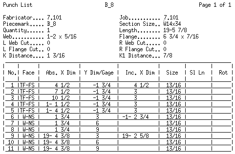
Description: A Standard Punch List identifies the location and size of holes, slots and marks. It can serve as a check list for guiding punching/drilling operations. The report may be used for fabrication machines not supported by the CNC Module. Or it may be used to double-check downloads from the CNC Module. You can output a Standard Punch List for wide flange , channel , angle , tube , S shape , plate , flat bar , W tee , S tee , cold formed channel or cold formed Z . A separate report is output for each material that you select. The report files are named for the selected materials and given a ".txt" extension.
Setup: You can output a Standard Punch List regardless of the " CNC configuration type " that is associated with your current " CNC configuration ." For example, you can output a Standard Punch List if the " CNC configuration type " is ' Cope Report ' or ' Peddinghaus 3 Spindle ' or etc. Be aware that the " CNC configuration type " you select does affect verification .
CNC contents | CNC main menu | report selection | top
Material information on the report :

Fabricator: The name of the current Fabricator . To change to a different Fabricator , Home > press "fabname" > double-click the Fabricator you want.
Job: The name of the current Job that the punch list pertains to.
Piecemark: A member piecemark or submaterial mark .
If you generated this report by detail or detail sheet, the piecemark listed here is a member piecemark , and the fabrication information presented in the report is for the main material of that member.
If you generated your report by submaterial or gather sheet, the piecemark listed here a submaterial mark .
Section Size: The shape " Description " that conventionally describes the material.
| Section naming : || wide flange || channel || angle || tube || S_shape || plate || flat bar || W tee || S tee || cold formed channel || cold formed Z || |
For materials other than plates or flat bars, this section size must be present in your Job's local shape file for it to be included here.
Quantity: The total number of pieces of the member main material or submaterial whose member piecemark or submaterial mark is printed at the top of the report.
Note: There are cases where the member piecemark will have a different quantity than you would get were you to generate this same information for the submaterial mark. This happens when the main material for one member is exactly the same submaterial used for a different member (for instance, in a different sequence).
Length: The overall length of the material. This information comes from the 3D model . If " Dimension from saw length " is checked and cuts that shorten the length of the material have been made, the saw length (longer, pre-cut length) is reported instead of the final length.
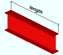
Web: Web depth x web thickness . This applies to wide flange , channel , angle , tube , S shape , cold formed channel and cold formed Z . For a plate or flat bar , this says "Size" instead of "Web" and the width x thickness is reported. The information comes from the local shape file .
| d = depth |

|
| tw = web thickness |

|
Flange: Flange width x flange thickness . This applies to wide flange , channel , angle , tube , S_shape , W tee , S tee , cold formed channel and cold formed Z . The information comes from the local shape file .
| tf = flange thickness |

|
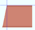
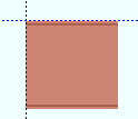
L Web Cut: The angle (in degrees) of the cut to made on the left end of the material's web. 0 means no cut has been made. This information comes from the 3D model .
-10 degrees
 |
0 degrees
 |
10 degrees
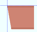 |
R Web Cut: Same as " L Web Cut ," except that this applies to the right end of the material.
- 10 degrees
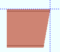 |
0 degrees
 |
L Flange Cut: The angle (in degrees) of the cut to made on the left end of the material's flange. 0 means no cut has been made. This information comes from the 3D model .
-10 degrees
 |
0 degrees
 |
10 degrees
 |
R Flange Cut: Same as " L Flange Cut ," except that this applies to the right end of the material.
- 10 degrees
 |
0 degrees
 |
K Distance: The distance from the bottom of the radius of the W , S , L or C section to the top of the flange. This applies to wide flange , channel , angle , tube , S_shape , cold formed channel and cold formed Z . This information comes from the local shape file .
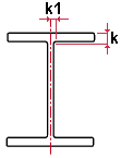 k = k distance
K1 Distance: The distance from the web center line to the edge of the radius of a W , S , C or L section.
 k1 = k1 distance
CNC contents | CNC main menu | report selection | top
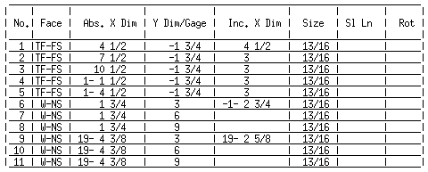
No: The number assigned to the hole, slot or marking operation described on this line.
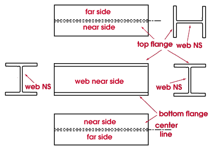
Face: The face of the material on which the operation is performed. W-NS = web, near side. TF-NS = top flange, near side. TF-FS = top flange, far side. BF-NS = bottom flange, near side. BF-FS = bottom flange, far side.
Abs X Dim: The absolute X dimension . This is the distance that the hole, mark or slot operation is from the left end of the material. This dimension is measured parallel with the length ( X axis ) of the material. If " Dimension from saw length " is checked and cuts on the left end of the material result in the total length of the material being shortened, then this distance is measured from the end of the cut material (instead of from the end as it existed before the cut).
Y Dim/Gage: The Y dimension (for web holes) or gage (for flange holes).
For a web hole, " Y Dim/Gage " is the distance that the center of the hole or mark is from the " Web hole reference point " that is set in Punch List Options .
Reference Point How " Y Dim/Gage " is measured Top flange From the top flange. Center of web From the half-depth line of the web. The reported value is negative (-) if the hole is on below the half-depth line, positive (+) if it is above the half-depth line. Bottom flange From the bottom flange. For a flange hole, " Y Dim/Gage " is the distance that the center of the hole or mark is from the " Flange hole reference point " that is set in Punch List Options .
Reference Point How " Y Dim/Gage " is measured Bottom of flange From the bottom edge of the flange. Web CL From the web center line. The reported value is negative (-) if the hole is on the far side of the center line, positive (+) if it is on the near side . Web face From the nearest face of the web. Top of flange From the top edge of the flange. Gage minus web This is the gage of the holes minus the web thickness.
Inc. X Dim: The incremental X dimension .
This is the distance parallel with the length ( X axis ) of the material from the previous operation to the center of the hole or mark being fabricated.
A positive (+) incremental X dimension signifies that the current operation is to the right of the previous operation. A negative (-) incremental X dimension signifies that the current operation is to the left of the previous operation.
In other words, the value reported here represents the distance and direction of tool travel from the last operation as measured parallel with the X axis of the material.
If the tool travels parallel with the Y axis only (not parallel with the X axis), this cell is left blank.
Size: The diameter of hole or slot being punched or drilled. " Sort hole size " in Punch List Options controls whether holes are listed from smallest-to-largest or from largest-to-smallest.

' 0 ' signifies a CNC mark .
Slot Ln: The slot length . This applies to slot operations only. This cell is left blank if the operation described in this line of the report is the fabrication of a round hole or CNC mark.

Rot: The rotation of the slot. This applies to slot operations only. This cell is left blank if the operation described in this line of the report is the fabrication of a round hole or CNC mark.
| <= X axis (material length) => |
|
|
0 ° rotation is parallel to the length ( X material axis ) of the material. A positive number signifies the number of degrees that the slot is rotated counterclockwise from the zero position.


