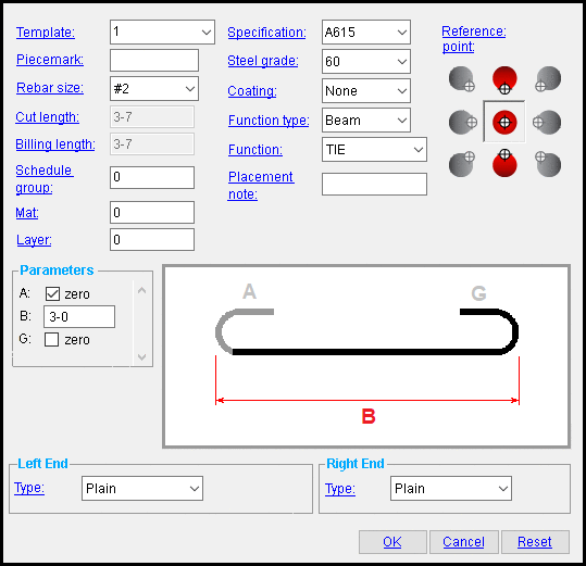
The Edit Rebar Shape window
Options :
To open this window :
- Add Material ( Modeling -- to add submaterial) of the type Rebar Layout or Shaped Rebar .
- Add Miscellaneous Member ( Modeling ) of the type Rebar Layout or Shaped Rebar .
- Edit One Material (with change options) (Set the selection filter to ' Rebar '.)
- Edit Multiple Materials (no change options)
- Double-click the material (to edit a material added using Add Material )
- "Edit Other" (to edit a material added using Add Miscellaneous Member )
- Double-click a material in the Model Tree
- Review 2D Items (non-editable, Drawing Editor )
Also see :
- Dimension precision (sets precision for distance entries)
- Submaterial piecemark (each unique material identified by)
- Submaterial detail (2D drawing of a material)
- Grayed out fields (indicate mixed entries or that the field is disabled)
- Altering a miscellaneous member's main view
------ General settings ------
| These settings apply to any rebar shape, regardless of whether the end " Type " is ' Plain ' or ' Threaded ' or ' Terminator ' or ' Deformed '. |
Template name: Read only or any character string (up to 61 characters). The template (if any) entered in the Standard Rebar Bends window whose shape operations match those of the rebar that you are adding to the model.
|
If there is a match but you would like to define another template, you may choose the option to " Create a new shape... " from the combo-box. The unique ' character string ' you enter here will be added to the list of templates in the Standard Rebar Bends window.
If there are no matching templates, you must enter a value here. The " Template name" cannot be left ' blank '.
If you edit the shape after you've added the rebar, the " Template name" field will be read-only.
Piecemark: Blank or any character string (up to 61 characters). This is the submaterial piecemark .
If this field is left ' blank ', then when this material is generated (after you press " OK "), SDS2 piecemarking looks for materials in the current Job that physically identical to this material and assigns to this material the same mark assigned to those materials. If no matching materials are found, piecemarking assigns this material a piecemark using the appropriate material mark prefix listed in Member and Material Piecemarking (setup).
Any ' character string ' that you enter must be unique. Validation does not let you enter a piecemark that has already been assigned to materials. If you are doing an Add Material or Add Miscellaneous Member , a piecemark entered here only applies if the material you are adding is unique -- if the material is exactly the same as previously added materials, the new material gets the piecemark of those previously added materials. On the other hand, if you are doing an Edit Material , all materials that are exactly like this material are re-assigned the unique mark you enter when this material is generated (after you press " OK "). The piecemark you enter remains a system piecemark , which means that it may be changed if you later edit a material just like this one and give that material a different piecemark.
Tip: If you want to change a submaterial mark, you should use Rename Project Items in Utility Options . That way all references to the submaterial mark are changed throughout the your current Job, even in Drawing Editor drawings.
Note 1: A submaterial mark is not yet assigned when this window appears during an Add material or Add Miscellaneous Member operation. A piecemark does appear in this field if you open this window using Edit Material or Review 2D Items . For the current quantity of materials assigned this piecemark, see the " Current quantity " listed on this material's General Information window.
Note 2: Two rebar shapes may have the same submaterial mark , but different submaterial mark index numbers , when certain " Left/Right end settings " are the same.
Report Writer: MemberMaterial.Material.MinorMark
Parametric module: MinorMark
Rebar size: Any size designation that has been entered to the Rebar Definitions Setup window under the " Active rebar standard " can be selected here.
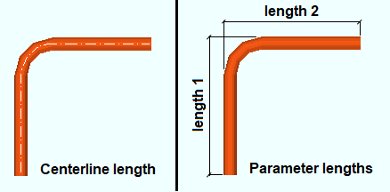
Cut length: This is a read-only information field that tells you the distance (in the primary dimension " Units ") of the material along its centerline from the farthest point on its left end to the farthest point on its right end. Unlike the " Bill length ", the cut length takes into account the bend curvature of the rebar. Below left is an example of a bent rebar shape showing the centerline distance from which the " Cut length " is derived.

The displayed value of the cut length of a reinforcing bar is the length of the centerline of its rebar shape material in the model when rounded.
Cut lengths are rounded to the ' distance ' specified for " Overall straight " or " Overall bent rebar " in the Rebar Definitions window.
Billing length: This is a read-only information field that tells you the sum of the distances (in the primary dimension " Units ") of the outermost extents of each segment. Each segment distance is a linear measurement in which the bend curvature of the rebar is not taken into account; however, when the rebar has hooks, the " Hook length " found in the Reinforcing Bar Definition window for bend shapes is added to this length. Above right is an example of a bent rebar showing the parameters from which the " Billing length " is derived.
The displayed value of the billing length of a reinforcing bar is equal to the sum of the lengths of its " Parameters " when rounded. (Parameter values, in turn, are rounded to the ' distance ' specified for " Segment " in the Rebar Definitions window.)
Billing lengths are rounded to the ' distance ' specified for " Overall straight " or " Overall bent rebar " in the Rebar Definitions window.
Note: " Billing length " is commonly referred to as "theoretical length."
Schedule group: Any non-negative integer with less than ten digits. Your choice of schedule group is not limited by any configuration option. The group applies to this member only -- see special case below.
Reason to assign a schedule group : The output of the Rebar List Report , Rebar in Member Report , and Bend Schedule custom reports can be limited to particular schedule groups. As a result, you can assign rebar shape material to different schedules, and create separate reports for rebar from each schedule.
A special case: You change the schedule group on this rebar shape. If you press " Yes " when prompted " Do you want regenerate... ," the changed schedule group is applied to ALL rebar matching the options checked in the Change All Options window.
User configuration: You can open the Report Manager window or the Table Edit window to copy, create, or edit rebar custom reports. " Edit " the report to add a comma-delimited list of schedule groups that the custom report will select.
Specification: A615 or A706 or etc. This is an ASTM specification entered into the Rebar Specifications window.
The " Steel grade " and " Coating " options are limited to the grades and coating entered into the Rebar Specification window for the selected ASTM specification.
Steel grade: 60 or 40 or etc. This is the yield strength (grade) of the rebar.
The grade choices in this list box are limited to those entered in the Rebar Specification window for the " Specification " chosen for this rebar shape.
Coating: None or a Coating designation that is available in the " Standard " that you have selected.
The coating choices in this list box are limited to those entered in the Rebar Specification window for the " Specification " chosen for this rebar shape.
Select ' None ' if you do not want a coating. Since it is possible to create specifications that do not have coatings, it is possible that ' None ' may be your only option.
User configuration: If a coating is not available for selection, selecting a different " Specification " will make that coating available if the coating you want is in that other standard. If you don't want to change to a different " Specification ," you can open the Rebar Specifications window and add the coating you want to the specification that you currently have selected.
Function type: None or Beam or Column or Footing or Slab or Wall .
This list box is populated automatically when the rebar is placed using a rebar component; for example, when placing a Rebar System .
Function: Blank or a usage description . The " Function " that you enter here is used on the schedules that appear on drawings.
The usage descriptions in this field are limited to those entered in the Rebar Usage Descriptions window for the " Function Type " chosen for this rebar shape.
User configuration: To add a " Function " that you can select here, type the function to a blank line in the ' Grade Beam / Continuous Footing ' section of the Rebar Usage Descriptions window.
Placement note: Blank or any string . A placement note (e.g., "@ 1-0 EW T&B") is appropriate here.
This field is automatically populated with a placement note when the rebar is placed using a rebar component; for example, a Rebar System .
Parameters: zero or a distance . The distances reported in these fields are the lengths (in the primary dimension " Units ") of reinforcing bar segments and hooks.
Segment length parameters include the outermost extents of each segment; these will include any bends in bent material. However, each segment distance is a linear measurement in which the bend curvature of the rebar is not taken into account. You may change the length of any rebar segment by entering a distance (in the primary dimension " Units " or other units ) of your own choosing into any length parameter field.
Hook length parameters
or
. When "
zero " is checked, a hook is not modeled (i.e., is zero-length). When "
zero " is unchecked, the hook length is calculated according the default parameters entered for the " Hook length " settings found in the Reinforcing Bar Definition window.
Displayed parameter values are rounded to the distance specified for " Segment " in the Rebar Definitions window.
------ Left/Right end settings ------
| This material's left end is the end where the first work point of the material was located when placing a rebar layout or shaped rebar . This first work point is also this material's 0,0,0 point in the material coordinate system. The point is identified by the origin reference point symbol at the beginning of a Material Rotate operation. |
Type: Plain or Threaded or Terminator or Deformed . The following illustration shows how the Modeling program represents rebar when it is displayed in solid opaque form:
|
|
|
Note that selecting ' Threaded ' only changes the color of the rebar end. The threads are not modeled.
' Plain ' and ' Deformed ' end types have no options of their own.
' Plain ' is the only available option for an end with a hook.
------ Threaded ------
| These settings apply when ' Threaded ' is selected as the end " Type ". |
Thread type (handedness): Right handed or Left handed . Neither option changes the visual appearance of the threaded end in the model.
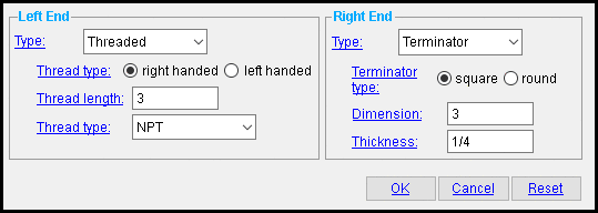
Thread length: The distance (in the primary dimension " Units " or other units ) from the left or right end of the rebar to where you want the threaded area to end. The following illustration shows how the Modeling program represents the threaded area when the round bar is displayed in solid opaque form.

|
tl = thread length |
Thread type (taper): NPT (National Pipe Tapered) or tapered threads. Neither selection changes the visual appearance of the threaded end in the model.
------ Terminator ------
| These settings apply when ' Terminator ' is selected as the end " Type ". |
Terminator type: Square or Round .
| type | shape |
| Terminator
(Square) |

|
| Terminator
(Round) |

|
Dimension: A distance (in the primary dimension " Units " or other units ).
When the " Terminator type " type is ' Square ' , the distance is the length or width of the square.
When the " Terminator type " is ' Round ' , the distance is a diameter . A diameter is measured from one edge of a circle, through its center, to its opposite edge.

|
d = termintator dimension |
Thickness: A thickness (in the primary dimension " Units " or other units ). This distance is measured parallel with the rebar.

|
t = termintator thickness. |
To close this window :
![]()
![]()
![]()
"OK" (or the Esc key or the ![]() button) closes the Edit Rebar Shape window and applies the settings on it to the material(s).
button) closes the Edit Rebar Shape window and applies the settings on it to the material(s).
If you opened this window to edit one or more rebar shapes ( single-edit or multi-edit ), the Change All Options & Warning List opens after you press the " OK " button. You can use that window to cancel your changes or, if other materials with the same submaterial piecemark exist, apply your changes to those other materials.
"Cancel" (or the Esc key) closes this window without saving any changes and ends the operation.
"Reset" undoes all changes made to this window since you first opened it. The window will remain open.
Note: For an Add Material or Add Miscellaneous Member operation, the settings you get when this window first opens are the settings of the most recently changed or added grating.


