 Exporting a STEP model
- General Overview
- Step-By-Step
- Tips and Tricks
- Related Tools
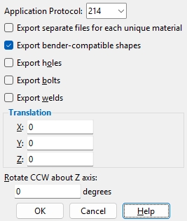
Application protocol: 203 or 214 or 242 . 203 outputs a file that conforms to AP203, which is the more basic protocol. 214 conforms to AP214, which includes most everything in AP203 but adds colors. 242 combines the capabilities of AP203 and AP214. Most software that can import STEP models can accept any of these formats. AP242 is the most recently developed protocol, and it may be required by newer software.
Export separate files for each unique material: ![]() or
or ![]() . If this box
. If this box ![]() is checked, individual part files will be exported and named with their material piecemark. If this box
is checked, individual part files will be exported and named with their material piecemark. If this box ![]() is not checked, a single .stp file will be created when performing a STEP export.
is not checked, a single .stp file will be created when performing a STEP export.
Note: In the Export Model window, the Output file name field is used to generate the name of the folder into which these files are placed.
Export bender-compatible shapes: ![]() or
or ![]() . If this box
. If this box ![]() is checked, Export Model attempts to export members as profiles with extruded shapes. If the box
is checked, Export Model attempts to export members as profiles with extruded shapes. If the box ![]() is not checked, the STEP export accurately renders curved shapes is a fashion that is similar to the way that they are rendered in the SDS2 model.
is not checked, the STEP export accurately renders curved shapes is a fashion that is similar to the way that they are rendered in the SDS2 model.
Export holes: ![]() or
or ![]() . If this box
. If this box ![]() is checked, holes are output to the STEP file. If the box
is checked, holes are output to the STEP file. If the box ![]() is not checked, holes will not be output to the file.
is not checked, holes will not be output to the file.
Export bolts: ![]() or
or ![]() . If this box
. If this box ![]() is checked, bolts are output to the STEP file. If the box
is checked, bolts are output to the STEP file. If the box ![]() is not checked, bolts will not be output to the file.
is not checked, bolts will not be output to the file.
Export welds: ![]() or
or ![]() . If this box
. If this box ![]() is checked, welds are output to the STEP file. If this option
is checked, welds are output to the STEP file. If this option ![]() is not checked, welds will not be output to the file.
is not checked, welds will not be output to the file.
Translation: 0 or a positive/negative distance. Each member’s work points have specific global X, Y, and Z coordinates at both ends in the 3D model. To move all members in the exported file by a set amount along X, Y, and/or Z, enter that distance here.
0 for X and Y and Z exports a model with the same origin ( 0, 0, 0 global coordinate ) as the model in your current Job.
A positive distanceadds to the X, Y or Z coordinates of all exported members.
A negative distancesubtracts from the X, Y or Z coordinates of all exported members.
Rotate CCW around Z axis: A positive or negative (-) number of degrees. Rotation is around the Z global axis . A value of 0 designates no rotation of the STEP model. A positive number rotates the STEP model counterclockwise that number of degrees. A negative number rotates the STEP model clockwise that number of degrees.
OK (or the Enter key) closes this screen and applies the settings.
Cancel (or the Esc key) closes this screen without saving any changes.
1 . Click the Export Model icon, which is pictured above. The icon can be found on the Import/Export page > Model section.
Method 2: Click Export Model on the home screen. The command can be found on the Export tab in the 3D section. Skip step 2.
Alternative: Use the Find Tool by searching the command name and clicking the Export Model icon, which is pictured above.
Learn more about alternative methods for launching commands.
2 . The status line prompts Select members, and the Select - Pan - Menu mouse bindings become active. Select the member(s), then press Enter or right-click and select OK.
Alternative: Press the Esc key or right-click and select Cancel to end the command.
3 . The Export Model window opens. Select STEP as the Export file format. Set the Destination where you want the file to be sent. Directory outputs the file to a folder. Select Properties to open the STEP Properties window (as shown on the General Overview tab).
4 . Select OK to export the .stp file.
Alternative: Press the Esc key or select Cancel to end the command.

